에너지 공급 및 저장 시스템인 리튬 이온 배터리(LIB)는 전자 제품, 전기 자동차 및 유틸리티 그리드에 널리 사용되었습니다. 그러나, LIB의 에너지 밀도를 향상시키기 위한 요구가 증가하고 있다. 따라서 에너지 밀도가 높은 새로운 전극 재료의 개발이 중요해지고 있습니다. 많은 신규 물질이 발견되었지만, (1) 바인더와 활물질(금속 산화물, Si, Li, S 등) 사이의 약한 상호 작용 및 계면 문제, (2) 큰 부피 변화, (3) 문제가 남아 있습니다. ) 낮은 이온/전자 전도도 및 (4) 충전 및 방전 과정 동안 활성 물질의 자가 응집. 현재 바인더가 없는 전극은 위의 문제를 해결할 수 있는 유망한 후보입니다. 첫째, 활물질을 전도성 기판에 직접 고정함으로써 바인더와 활물질의 계면 문제를 해결할 수 있다. 둘째, 활물질의 큰 부피 팽창은 바인더가 없는 전극의 다공성에 의해 수용될 수 있다. 셋째, 전도성 기판과 활물질의 밀착에 의해 이온 및 전자의 전도성을 높일 수 있다. 따라서 무바인더 전극은 일반적으로 우수한 전기화학적 성능을 나타낸다. 전통적인 제조 공정에는 전기화학적으로 비활성인 바인더와 전도성 물질이 포함되어 있어 활성 물질의 비용량과 에너지 밀도를 감소시킵니다. 바인더와 도전재를 제거하면 전지의 에너지 밀도를 크게 향상시킬 수 있다. 이 리뷰는 바인더가 없는 전극의 준비, 적용 및 전망을 제시합니다. 먼저, 활성 물질의 캐리어 역할을 하는 다양한 전도성 기판이 도입됩니다. 그 다음은 화학, 물리학, 전기의 관점에서 바인더가 없는 전극 제조 방법입니다. 이어서, 플렉서블 전지 분야에서의 무바인더 전극의 응용을 제시한다. 마지막으로 이러한 처리 방법 및 응용 프로그램의 관점에서 전망을 제공합니다.
소개
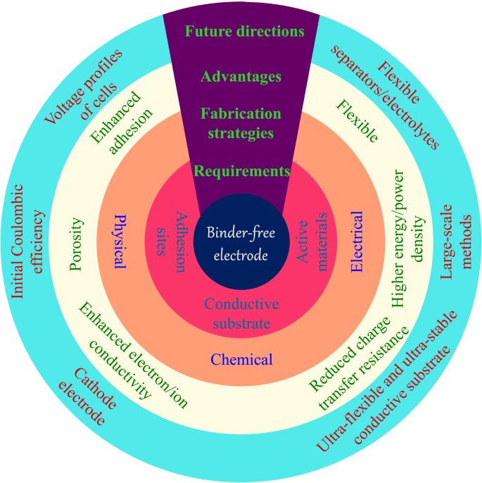
에너지 위기와 환경 문제는 재생 에너지와 새로운 환경 친화적인 에너지 저장 시스템의 개발을 주도했습니다. 풍력, 수력, 태양광 등 재생에너지의 간헐적인 문제로 인해 배터리는 중요한 에너지 저장 시스템으로 인식되고 있다[1,2,3]. 안정적이고 효율적인 에너지 저장 장치에 대한 요구가 증가하고 있습니다. 리튬 이온 배터리(LIB)는 높은 에너지 및 전력 밀도, 높은 셀 전압, 넓은 작동 온도 범위 및 긴 수명으로 인해 많은 관심을 받았습니다[4]. 최근 전지 제조의 전통적인 공정은 폴리비닐리덴 플루오라이드(PVDF)를 바인더로 사용하여 코팅 방법에 의해 집전체에 도전제 및 활물질을 고정시키는 것이다[5, 6]. 고용량 및 더 작은 크기의 LIB에 대한 수요로 인해 고용량 활성 물질의 개발과 전지 내 비활성 물질의 감소가 모두 중요합니다. 불활성 물질을 줄이는 방법은 다음과 같다. 첫째, 기존의 바인더는 전도성 바인더, 예를 들어 파이렌 기반 폴리머 및 폴리플루오렌 공액 폴리머로 대체될 수 있습니다. 이러한 폴리머는 자연적으로 전도성이며 측쇄 또는 골격이 변형되어 접착력을 증가시킵니다[7,8,9,10]. 전도성 바인더는 전도성 에이전트 역할을 합니다. 따라서 세포 내에서 불활성 탄소의 사용을 줄일 수 있다. 그러나 이러한 결합제(PVDF 및 새로 개발된 결합제 모두)와 활성 물질(금속 산화물, Si, Sn, Li, S 등) 사이의 약한 계면 상호작용으로 인해 입자가 자가 응집되거나 집전체로부터 분리됩니다. 따라서 이러한 고용량 신소재는 배터리 성능이 저하됩니다[11,12,13,14,15]. 두 번째로 탄소천, 그래핀, Ni 발포체와 같은 첨단 전도성 기판을 조사하여 기판의 특수 접착 부위에 활물질을 고정할 수 있습니다. 활성 물질과 기판 사이의 접착은 강력한 화학적 및/또는 물리적 결합에 의해 이루어지며, 이는 전극의 무결성을 크게 향상시킵니다. 게다가, 이 공정은 잠재적으로 바인더와 전도성 탄소 첨가제를 모두 제거합니다. 따라서 에너지 밀도를 크게 향상시킬 수 있다[16, 17](그림 1).
<그림>
바인더가 없는 전극의 요구 사항, 제조 방법, 장점 및 향후 개발
많은 연구에서 바인더가 없는 전극의 수많은 장점이 입증되었습니다[18,19,20,21]. 활성 물질을 해당 전자 전도성 기판에 고정함으로써 활성 물질 표면을 덮는 유기 결합제가 없기 때문에 결합제와 활성 물질의 계면 문제를 해결할 수 있습니다[22, 23]. 활물질이 전도성 기판에 단단히 부착되어 전자 전도성이 크게 향상됩니다. 다공성 구조와 같은 지지 물질의 특성은 전해질 침투 및 이온 확산을 촉진합니다[24]. 게다가, 넓은 표면적은 활물질의 완전한 사용과 리튬 이온의 수송을 위한 이점이 있습니다. 또한, 활물질은 일반적으로 전도성 기판에 균일하게 고정되어 나노 입자의 덩어리를 효과적으로 방지하고 반복되는 사이클링 과정에서 부피 팽창을 줄일 수 있습니다. 바인더가 없는 전극은 일반적으로 높은 Li
+
를 나타냅니다. 및 전자 전도성, 적절한 전해질 습윤성 및 큰 부피 팽창 공간 및 강한 결합 강도. 따라서 바인더가 없는 전극은 PVDF/활물질/카본 블랙 시스템보다 더 나은 용량, 사이클링 및 속도 성능을 나타냅니다. 특히, 새로운 나노물질의 사이클 수명은 ~ 10 Ag
−1
의 높은 전류 밀도로 수십 사이클에서 수백 사이클로 증가했습니다. .
활물질의 담체로서의 전도성 기판은 무바인더 전극의 기본이다. 전도성 매트릭스는 활성 물질을 성장시키기에 적합한 위치를 가져야 하며 기계적 특성은 적용에 결정적인 역할을 합니다. 웨어러블 및 플렉서블 전자 장치에 전극을 적용하려면 전도성 기판을 여러 번 구부리거나 접힐 수 있어야 합니다. 이것은 슬러리 공정에 의해 제조된 종래의 전극에서 달성하기 어렵다. 주된 이유는 굽힘 과정에서 활물질이 집전체에서 분리되어 배터리가 비활성화되기 때문입니다. 유연한 네트워크에서 직접 활성 물질을 성장시키면 강력한 상호 작용을 제공하고 높은 에너지 밀도를 유지하는 견고한 전극으로 이어집니다. 이러한 유연한 기판에는 주로 금속 폼, 탄소 천 및 탄소 재료의 독립 필름이 포함됩니다[25].
이 검토는 LIB용 바인더가 없는 전극의 준비, 적용 및 전망에 대한 개요를 제공하는 것을 목표로 합니다. 우리의 목표는 바인더가 없는 전극의 최근 개발 및 개선 사항을 강조하는 것입니다[26]. LIB 분야에서 의심할 여지 없이 중요한 닥터 블레이드 캐스팅 및 침투 방법은 포함되지 않습니다. 먼저, 주로 활물질의 캐리어 역할을 하는 다양한 전도성 기판을 소개합니다. 우리는 화학, 물리학 및 전기의 관점에서 바인더가없는 전극 제조 방법에 대한 프레젠테이션을 따릅니다. 이어서, 플렉서블 전지 분야에서의 무바인더 전극의 응용을 제시한다. 마지막으로 이러한 준비 방법 및 응용 프로그램과 관련된 주요 문제가 예상됩니다.
전도성 기판
전도성 기판은 전자 전도성이 좋은 집전체입니다. 따라서 재료는 일반적으로 금속 또는 탄소 재료로 구성됩니다. 제조상의 한계로 인해 금속 집전체는 일반적으로 필름, 메쉬[27] 및 발포체[28]로 제작됩니다. 금속 제품은 일반적으로 단단하고 변형 후 쉽게 회복되지 않습니다. 따라서 슬러리 기반 배터리와 동일한 구성의 고에너지 밀도 배터리에만 적합합니다. 구리와 알루미늄은 산화 저항이 다르기 때문에 각각 음극 및 양극 집전체로 사용됩니다[29]. 금속폼은 경량, 대면적, 3차원 구조 등의 장점이 있어 바인더가 없는 전극에 많이 사용된다[30].
탄소 재료는 다양한 출처에서 유래하며 준비 과정에서 매우 유연합니다[31]. 이러한 물질은 화학적으로 제조된 탄소 나노튜브, 그래핀 및 유기 물질로부터 다공성 탄소 구조뿐만 아니라 자연에 존재하는 다양한 생물학적 물질로부터 유도될 수 있다[17, 32]. 금속에 비해 일부 탄소 재료는 무게가 가볍고 유연성이 뛰어납니다(유연성, 접을 수 있는 등). 탄소 천은 우수한 전기 전도성과 유연성으로 인해 에너지 저장 분야에 점점 더 많이 사용되고 있습니다[33].
화학적 방법
온열 치료
열처리는 바인더가 없는 전극을 제조하는 일반적인 방법 중 하나입니다. 이 방법은 가열 및 냉각 과정을 통해 재료의 물리적, 화학적 특성을 변경하는 것입니다. 열처리 후 무기염은 상응하는 금속 산화물로 전환되고 폴리머는 탈수되어 탄소 전도성 구조를 형성합니다(그림 2). 바인더가 없는 전극을 제조하기 위해 일반적으로 열처리를 통해 활물질을 고정시키거나 자립형 백본을 구성합니다.
<그림>
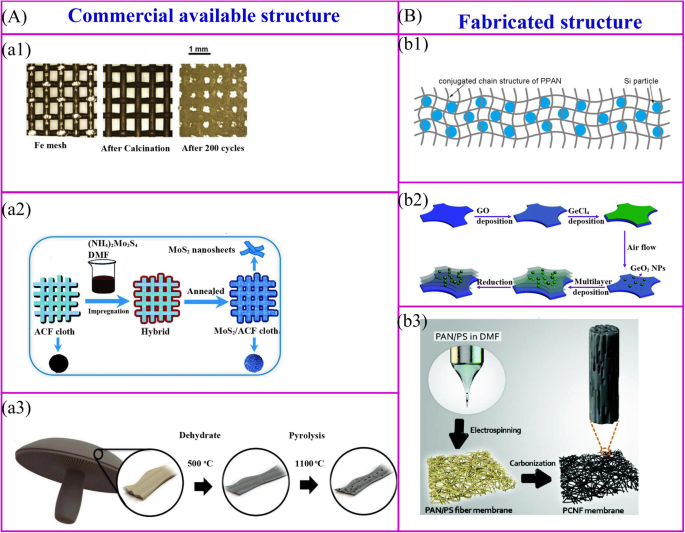
상업적으로 이용 가능한 구조에 대한 열처리(a ) 및 조작된 구조(b ). a1 금속 산화물 나노 입자는 간단한 열 산화 과정을 통해 금속 구조의 표면에서 얻을 수 있다[34]. a2 활성 물질은 열처리에 의해 전도성 구조의 표면에서 합성될 수 있다[35]. a3 바이오매스는 탄소 구조를 달성하기 위해 탄화될 수 있다[32]. b1 폴리머와 활성 물질의 혼합물은 바인더가 없는 전극을 얻기 위해 탄화될 수 있습니다[36]. b2 계층 구조는 여러 프로세스를 통해 얻을 수 있습니다[37]. b3 Binder-free 전극은 전기방사막을 열처리하여 얻을 수 있다[38]
상업적으로 이용 가능한 구조는 활성 물질을 고정하기 위한 지지 골격으로 활용됩니다. 이러한 재료는 금속 메쉬, 탄소 섬유, 상업용 스폰지, 생물학적 파생물 및 상업용 스폰지 등으로 구성됩니다(그림 2a). 금속 산화물 나노 입자는 간단한 열 산화 과정을 통해 금속 집전체 표면에서 합성될 수 있다[34](그림 2a1). 추가 처리 없이 이러한 집전체를 바인더가 없는 LIB의 지지 재료로 직접 사용할 수 있습니다. 철망 지원 Fe2 O3 1050 mAh g
−1
의 매우 높은 방전 용량을 보여줍니다. 200 사이클 후. 전구체의 활물질 용액으로 전도성 멤브레인을 열처리하는 것은 바인더가 없는 전극을 제조하기 위해 널리 개발된 방법입니다(그림 2a2). 대표적인 예는 초박형 MoS2 활성탄소섬유(ACF) 천의 표면에 코팅된 나노시트는 (NH4 )2 모스4 어닐링이 뒤따르는 용액. 전기화학적 성능은 971 mAh g
−1
의 방전 용량이 입증되었습니다. 100 mA g
−1
의 전류 밀도에서 달성됩니다. [35]. 바이오매스 재료의 열처리는 바인더가 없는 전극을 제조하는 간단한 방법입니다. Ozkan과 동료들은 포토벨로 버섯을 바인더가 없는 LIB 양극으로 탄화했습니다(그림 2a3)[32]. 고온에서 바이오매스 재료의 구조가 남을 수 있고, 자연적으로 존재하는 헤테로원자 및 금속 이온이 탄소 재료에 도핑될 수 있어 전자 전도도 및 용량과 같은 전기화학적 성능을 증가시킨다.
고분자는 바인더가 없는 전극의 자립형 골격을 구성하는 주재료이며 골격구조는 고분자와 고분자의 제조방법에 따라 결정된다(Fig. 2b)[40]. 첫째, 일반 고분자의 경우 고분자-활물질 복합막을 550℃에서 열분해하면 바인더가 없는 전극을 제조할 수 있다(그림 2b1)[36]. Si/SiOx /PAN 복합 전극은 이 방법으로 제조됩니다[41, 42]. 어닐링 후 폴리아크릴로니트릴(PAN)은 N-도핑된 전도성 구조로 전환될 수 있으며 탄소 네트워크는 SEI를 안정화하고 부피 변화를 수용할 뿐만 아니라 전극에 우수한 유연성과 기계적 강도를 제공합니다. 유사하게, Si/rGO 전극은 Si, 환원그래핀옥사이드(rGO) 및 폴리비닐피롤리돈(PVP) 현탁액을 니켈 폼에 주조한 후 어닐링 공정을 통해 얻을 수 있습니다[43]. 둘째, LBL(Layer-by-Layer) 공정은 복잡한 구조와 나노물질을 만드는 매력적인 방법입니다. 폴리(디알릴디메틸암모늄 클로라이드)(PDDA) 용액, 그래핀 옥사이드(GO) 현탁액, PDDA 용액 및 수성 H3에 Ti 호일을 침지하여 다중 층을 갖는 전극을 제작할 수 있습니다. PMo12 O40 특정 주기에서 500°C에서 열처리가 뒤따릅니다[44]. 이러한 LBL 방법은 바인더가 없는 전극을 대규모로 제조하는데 적용될 수 있다. 이러한 종류의 방법은 메조다공성 아나타제 TiO2를 만드는 데 적합합니다. /니켈 폼 [45], MoS2 나노시트/ACF 및 다층 GeO2 /rGO(그림 2b2) [37, 46]. 마지막으로, 바인더가 없는 전극은 활성 물질을 고분자로 캡슐화한 다음 새로운 나노구조로 제작하여 제작할 수 있습니다(그림 2b3). 유연한 계층적 나노섬유 매트는 전기방사 및 후속 열처리에 의해 합성될 수 있습니다.
상업적으로 이용 가능하고 제작된 구조에 대한 많은 장점이 있습니다. 시판되는 구조체의 표면에는 활물질이 코팅되어 있고, 제작된 구조체는 활물질을 캡슐화하는 용기 역할을 한다. 활물질의 캡슐화와 달리 표면 코팅은 활물질과 전해질의 더 많은 접촉을 만듭니다. 따라서 속도 성능은 향상되지만 초기 쿨롱 효율이 낮아지고 사이클링 성능이 저하됩니다.
열수 처리
열수 방법은 지난 수십 년 동안 다양한 분야에서 널리 사용되었습니다. 현재 이 기술은 메커니즘 해석 및 재료 제작 측면에서 많은 노력을 기울였습니다. 열수 공정의 경우 금속 이온이 용액에 용해되어 고온 및 고압에서 과포화 용액을 형성합니다. 이 과정에서 기판의 핵 생성 지점에서 결정 성장이 발생합니다. 열처리에 의해 제조된 응집 입자와 비교하여, 열수 방법은 온화한 조건에서 고순도, 균일, 단분산 및 제어 가능한 나노 규모 물질을 생성할 수 있습니다. 미세 나노구조의 열수 공정은 에너지 저장 재료에서 널리 주목받고 있습니다.
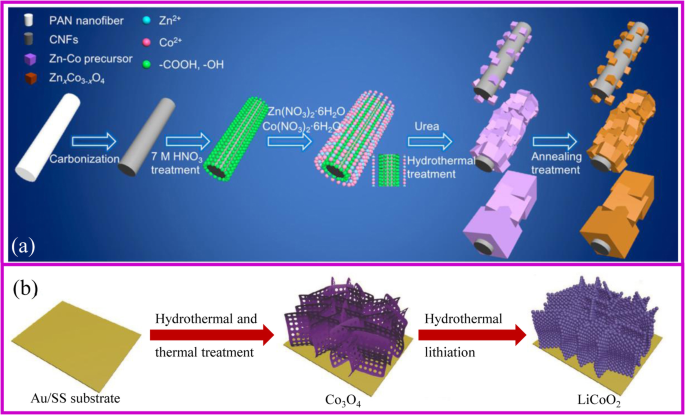
열수법을 사용하여 바인더가 없는 전극을 제조하기 위한 전체 합성 공정은 그림 3a에 설명된 절차와 유사합니다. 지원 자료를 먼저 얻습니다. 지지 재료가 핵 생성 지점이 제한되어 매끄럽다면 표면에 활성 재료의 침착이 금지됩니다. 일반적으로 탄소포는 더 친수성이 되려면 산성 또는 열처리가 필요합니다. 또한, 용액의 pH는 기질 표면에서 전구체의 성장을 촉진하기 위해 적절한 침전제를 첨가하여 조정해야 합니다. 얻어진 물질을 열처리하여 나노구조를 유지하면서 원하는 복합체를 얻는다. Hu, Zhang 및 동료들은 Znx 준비를 위한 확장 가능한 방법을 보고했습니다. 공동3-x O4 나노큐브/CNF(탄소 나노 섬유, CNF). 큐브의 크기는 열수 과정에서 적용되는 pH에 의해 조정될 수 있습니다[47].
<그림>
아 ZnCoOx의 계획 /CNF 복합 제조 [47]. ㄴ 열수법을 이용한 캐소드 전극 제조 [48]
열수 방법은 단일 및 다중 구성요소를 제작할 수 있습니다[49]. TiO2와 같은 바인더가 없는 전극의 많은 형태가 개발되었습니다. 탄소 나노튜브(CNT) 스캐폴드의 나노로드 [50], Fe3 O4 나노입자, NiO 나노콘, Ni(OH)2 나노시트 및 Fe3 O4 /Ni 폼에서 성장된 Ni/C 나노플레이트 [51,52,53,54], MnO2 그래핀 폼의 나노플레이크[55] 및 FeF3 ·0.33H2 O 탄소 섬유의 꽃 모양 어레이 [56]. Li와 동료들이 NiCo를 성장시켰습니다2 S4 NiCo2 S4 나노튜브는 길이가 5 nm이고 너비가 100 nm입니다[57]. 다공성 NiCo2 O4 NiCl2을 사용하여 3D 그래핀 네트워크에서 성장한 나노바늘을 얻을 수 있습니다. ·6H2 O 및 CoCl2 ·6H2 O 전구체로서 [58]. 이러한 나노구조는 전도성 기판에 균일하게 분포됩니다. 따라서 이러한 복합 재료는 방전/충전 과정에서 전자 전달을 촉진하고 활물질의 부피 변화를 수용할 뿐만 아니라 LIB의 고용량, 높은 속도 성능 및 사이클링 안정성으로 전기 화학적 특성을 향상시킵니다. 특히 Fe3 O4 nanoparticle@Ni foam은 543 mA h g
−1
의 가역 용량을 나타냈습니다. 2000회 이상 사이클 후 10 C의 전류 밀도에서 [51]. NiO arrays@Ni 폼은 969 mAh g
−1
의 용량을 제공할 수 있습니다. 0.5 C의 전류 밀도에서 여전히 약 605.9 mAh g
−1
유지 10 C [52]에서.
열수 방법은 음극 재료용 금속 산화물의 리튬화를 달성하기 위한 좋은 전략이라는 점은 주목할 가치가 있습니다. 기존의 리튬화는 전구체와 Li 염의 균일한 혼합을 필요로 하며, 이는 원하는 바인더가 없는 전극을 얻기가 매우 어렵습니다. 열수 리튬화는 전구체의 처리가 필요하지 않은 용액법으로 바인더가 없는 캐소드 전극을 제조할 수 있는 매력적인 방법 중 하나이다. 2018년 Xia et al. 다공성 LiCoO2 준비 Co3의 열수 리튬화에 의한 기판으로 Au 코팅된 스테인리스 스틸을 사용한 바인더 없는 음극 O4 전구체(그림 3b) [48]. 이 전극은 104.6 mA h g
−1
용량으로 우수한 속도와 사이클링 성능을 보여줍니다. 10 C 속도 및 1000회 주기 후 용량 유지율 81.8%에서.
화학 욕조 증착
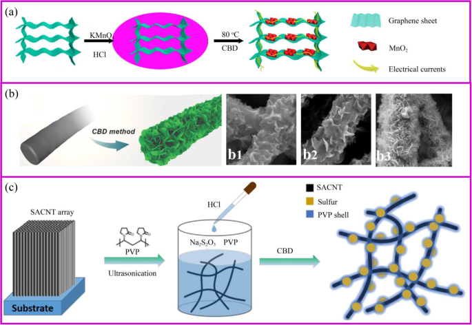
CBD(Chemical Bath Deposition)는 화학 반응을 통해 기판에 활성 물질을 제자리에서 성장시키는 과정입니다. 열수법에 비해 이 합성법은 스케일업이 용이하고 특별한 장비를 사용하지 않고도 낮은 온도와 상압에서 나노물질을 성장시킬 수 있다. 또한 CBD와 수열법은 유사한 메커니즘을 통해 기판 표면에서 물질을 성장시키므로 기판에 대한 요구 사항이 매우 유사합니다. 도 4a에 도시된 과정과 동일하게 반응의 pH와 온도를 조절함으로써 활물질의 전구체가 핵을 형성하고 성장하게 된다. 예를 들어, 3D 그래핀/MnO2 하이브리드는 산성 KMnO4에서 3D 그래핀 에어로겔의 존재에 의해 준비됩니다. 솔루션 [59].
<그림>
아 3D 그래핀/MnO2 준비의 개략도 하이브리드 및 3D 그래핀/MnO2에서 전자 이동의 그림 하이브리드 [59]. ㄴ CNF@Ni(OH)2의 제조를 위한 CBD 방법 [60]. b1–3 Ni(NO3 농도 증가에 따른 다양한 하이브리드 멤브레인 )2 해결책. ㄷ PVP@S-SACNT 합성물의 합성 절차 개략도 [61]
활물질의 형태는 지지 물질, 반응 시간 및 전구체 농도에 의해 영향을 받습니다(그림 4b). 기질은 초기 핵형성 부위를 결정합니다. 예를 들어, MnO2의 형태 는 각각 그래핀과 탄소나노튜브의 기판에 나노시트와 나노입자이다[62, 63]. 또한, 지지체 상의 활물질의 형태는 전구체 농도에 의해 영향을 받는다. 예를 들어 얇은 Ni(OH)2 나노시트는 낮은 Ni(NO3에서 나노섬유 표면에 수직으로 형성 및 성장하기 시작합니다. )2 농도(그림 4b) [60]. 그러나 Ni 염 농도가 증가함에 따라 Ni(OH)2의 두꺼운 층이 Ni(OH)2의 빠르고 균질한 핵 생성에 기인할 수 있는 나노시트가 점진적으로 형성됩니다. . 따라서 지지체 상의 활물질의 형태는 입자[64], 외피, 나노시트[65], 나노와이어[66, 67]와 같이 다양할 수 있다. 열수법으로 제조된 전극과 유사하게, 나노스케일 재료를 사용한 다공성 및 전도성 구조는 리튬 이온의 신속한 확산과 빠른 리튬화/탈리튬화를 위한 전자의 효율적인 수송을 위한 연속 채널을 제공할 수 있습니다.
매우 유망한 양극 재료인 황은 온화한 조건에서 CBD로 합성할 수 있습니다. 황 물질은 Na2 간의 간단한 반응을 기반으로 합니다. S2 O3 및 실온에서 수용액 중의 산. 이 과정은 간단하고 환경에 무해합니다. 적절한 템플릿이나 계면활성제를 적용하면 특수한 나노황 구조를 얻을 수 있다[68]. 전도성 물질이 S2를 흡수할 수 있는 경우 O3
2-
, 많은 양의 황이 계면에서 생성됩니다. 페닐 설폰화 작용기에 의해 변형된 그래핀은 제자리 산화환원 반응을 통해 황의 균일한 증착을 가능하게 한다[69]. 바인더가 없는 PVP 캡슐화된 황 전극은 황 나노입자를 전도성 네트워크에 제자리에 고정시켜 준비합니다(그림 4c). PVP는 분산제로 사용할 수 있는 소수성 알킬 사슬과 친수성 아미드기를 가진 양친매성 고분자입니다. 용액에 산을 첨가한 후 황이 형성되기 시작하면 PVP의 소수성 특성으로 인해 S 표면에 우선적으로 코팅되어 폴리설파이드 용해를 보호하기 위해 조밀한 층을 형성합니다[61].
화학적 증기 증착
화학 기상 증착(CVD)은 기체 물질이 뜨거운 기판 표면에 증착되는 화학 반응입니다. 이 방법은 촉매의 도움으로 3차원 구조와 나노와이어에 균일한 막을 생성할 수 있습니다. CVD 공정은 (1) 뜨거운 기판 표면에서 반응 가스의 확산 및 흡수, (2) 활성 부위에서 가스의 반응으로 코팅 물질 형성, (3) 배기 가스의 3단계로 구성됩니다. 생성된 가스. 온도, 압력, 가스비, 종류를 조절하여 원하는 코팅재를 얻을 수 있습니다.
CVD 방법은 활물질을 직접 성장시킬 수 있습니다. CVD 공정에 해당하는 인상적인 예가 Tay와 동료들에 의해 보고되었습니다[70]. 3D 니켈 폼/CNT 복합재는 니켈 폼을 기질로, 에탄올을 전구체 및 탄소원으로 사용하여 합성됩니다. 얻어진 CNT는 NiO 나노시트 성장의 증착을 위한 기판 역할을 합니다. 무정형 FeVO4 나노시트 어레이는 VCl3을 사용하여 유연한 스테인리스 스틸 기판에서 직접 성장할 수 있습니다. 선구자로. 601 mAh g
−1
의 가역 용량을 제공할 수 있습니다. 및 453 mAh g
−1
각각 8 C 및 15 C의 고전류 밀도에서 [71].
CVD에 의해 준비된 표면층은 또한 전극과 전해질 사이의 보호 인터페이스 역할을 합니다. Yang과 동료들은 에틸렌을 탄소 전구체로 사용하여 CVD 공정을 통해 활물질을 코팅했는데, 이는 구조의 안정성을 향상시킬 뿐만 아니라 우수한 전자 전도성 네트워크를 형성합니다. 탄소 코팅층이 있는 Si 나노와이어는 우수한 속도 성능을 보인다[72, 73]. 2016년 Cui et al. 등은 CVD 방법으로 제조된 친친수성 물질의 얇은 층을 가진 다공성 물질이 Li-ion의 균일한 증착을 촉진하는 지지체 역할을 할 수 있음을 보여주었습니다[74]. 이 소재는 3 mA/cm
2
의 높은 전류 밀도에서도 작은 과전압으로 안정적인 사이클링 성능을 보여줍니다. 충전 및 방전 과정에서.
CVD 방법은 고급 Si 재료의 제조를 위한 주요 전략 중 하나입니다. 실리콘은 4200 mAh g
−1
의 가장 높은 비용량으로 인해 차세대 LIB용으로 가장 유망한 양극 재료입니다. 낮은 작동 전압[75]. 그러나 실리콘은 부피 변화가 커서 사이클링 과정에서 고체 전해질 계면(SEI)의 지속적인 형성, 분쇄 및 용량 감소를 초래합니다[76]. 일반적으로 고급 실리콘 재료는 실리콘 입자를 후처리하거나 이산화규소를 환원하여 제조할 수 있습니다. CVD는 고순도 실란 또는 실란 대체물을 환원 또는 열분해하여 박막 또는 나노와이어 실리콘을 제조하는 바람직한 방법입니다. 2008년 Cui et al. Au 나노입자를 촉매로 사용하여 스테인리스강에 실리콘 나노와이어(Si NW)를 합성하기 위해 CVD 방법을 사용하여 LIB용 양극으로 성공적으로 적용했습니다[77]. 직경이 약 89 nm인 실리콘 나노와이어는 균열 없이 400% 부피 변화를 수용할 수 있습니다. 또한, 나노와이어는 집전체에서 직접 성장하며, 모든 나노와이어는 용량에 능동적으로 기여한다. 나노 구조로 인해 다공성 전극 전체가 매우 큰 비표면적을 가지므로 이온 전도도가 우수합니다. 나노와이어 실리콘 재료는 거의 4200 mAh g
−1
의 이론적 용량을 달성할 수 있습니다. C/20 비율로 처음으로. 나노와이어의 직경은 사이클링 과정 후 89에서 141 nm로 증가했지만 전체 구조는 손상되지 않았습니다. Si의 성장은 촉매에 의해 제어됩니다. 스테인리스 스틸은 또한 Si 필름 형성을 위한 촉매로 작용할 수 있습니다. 그러나, 집전체 상에 Si 층을 형성하면 Si 층과 집전체 사이에 심각한 응력이 발생할 수 있다. 활성 시드를 제어하여 특정 단계에서 Si의 성장을 방해할 수 있습니다. 예를 들어, 화학적으로 안정한 그래핀 또는 Au 또는 Sn 나노입자가 있는 금속 Ge 표면은 Si NW 성장의 씨앗 역할을 할 수 있습니다[78, 79].
원자층 증착
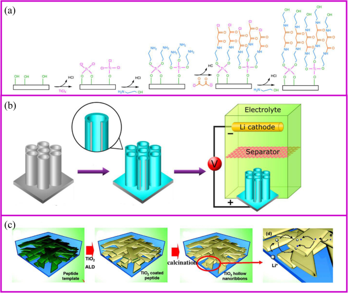
원자층 증착(ALD) 방법은 CVD와 유사한 기상, 자체 제한 및 층별 증착입니다. 이 방법은 원자 층별 증착에서 나노 규모의 제어 가능한 박막을 생성할 수 있습니다. 따라서 공정은 서로 반응할 수 있는 최소 2개의 서로 다른 전구체 가스로 구성되어야 합니다[80]. ALD 공정 동안 첫 번째 가스는 파이프로에 도입되고 기질과 반응하여 활성 그룹이 있는 코팅층을 형성합니다. 첫 번째 가스가 완전히 방출된 후 두 번째 가스가 도입되어 첫 번째 층과 반응합니다(그림 5a)[81]. 이 과정을 반복하면 다양한 코팅층을 얻을 수 있습니다. ALD에 의한 코팅막은 주로 기판, 가스 전구체, 온도 등에 영향을 받습니다. 기존의 박막 증착 방법과 비교하여 ALD는 화학 반응에 의해 기판 전체의 코팅 두께를 정밀하게 제어할 수 있으며 코팅층은 핀홀일 뿐만 아니라 - 자유롭고 조밀하고 균일하지만 복잡한 3D 구조에 증착된 경우에도 등각입니다. ALD의 이러한 특징은 나노기술 및 재료를 위한 탁월한 선택으로 제시합니다.
<그림>
아 ALD 기술 메커니즘 [81] 및 b에 대한 두 가지 예 표면 코팅 [82] 및 c 활물질 제조 [83]
ALD 준비된 전극은 일반적으로 우수한 전기화학적 특성을 가지고 있습니다. TiO2 가장 많이 연구된 전극 재료이다(그림 5b, c)[84]. 최근 SnO2 [85], MoS2 [86] 등이 준비되어 LIB의 활물질로 성공적으로 사용됩니다(그림 5c) [87, 88]. ALD는 기상 합성법이기 때문에 재료의 표면이나 기공 내부에 두께를 조절할 수 있는 균일한 층을 코팅할 수 있습니다. Kang 등[83]은 전극의 활물질인 나노리본이 전해질을 물질 내부에 잠기게 하여 리튬 이온의 확산 속도를 크게 증가시킴을 입증하였다. 템플릿의 도움으로 나노리본의 빈 공간은 폭이 거의 100–200 nm이고 높이가 20–50 nm인 터널 크기를 갖는 ALD에 의해 합성될 수 있습니다. 전해질이 빈 공간을 쉽게 적실 수 있습니다. TiO2의 속도 성능 나노 규모 네트워크는 100 nm-TiO2에 비해 5 C에서 최소 5배 증가했습니다. 나노 분말. Biener et al. TiO2로 코팅된 다공성 전극 레이어. 코팅층이 얇은 재료가 더 나은 속도 성능을 나타내는 것으로 나타났습니다. TiO2일 때 layer thickness increased from 2 to 7 and 20 nm, the capacity decreases from 227 to 214 and 157 mAh g
−1
, respectively [89].
The most general application of ALD in electrochemical storage is to protect the surface stability of electrodes to enhance the electrochemical performance [90]. The uniform Al2 O3 coating on TiO2 nanotubes for LIBs is the most representative example of surface protection (Fig. 5a) [82]. The coating thickness of the Al2 O3 layer onto the TiO2 nanotube can be controlled by ALD from 0.2, 1 to 10 nm according to the repeated cycles. The 1 nm coating Al2 O3 layer can suppress the SEI formation and undesirable side reactions, which greatly improves the capacity. In addition, Al2 O3 as an artificial layer can participate in the formation of SEI with Li–Al–O groups, which are great ionic conductor. Therefore, the Li-ion conductivity in improved and great rate performance can be achieved. Noked et al. demonstrated the 14 nm Al2 O3 layer can effectively improve the stability of lithium metal interface by avoiding the reactions with electrolyte, cathode shuttles, etc. [91]. Comparing with the bare lithium metal anode, the ALD-protected anode can significantly improve cycling performance.
Electrical Methods
Electroplating
Electroplating is a versatile technique that functions to improve the surface properties of materials or to prepare nanoscale structures. The deposition mechanism is that in the case of an applied electric field, the ions move to the positive electrode and are reduced on the surface of the substrate to form a film. The thickness of film is controlled by the current density and time. Through post-treatment, the metal film can be oxidized to the corresponding metal oxide.
Template synthesis is the most popular method for preparing nanostructures of various materials using electroplating in LIBs. Chen, Xia, and coworkers obtained porous CoO semisphere arrays using the polystyrene as the template [92]. Yan, Tong, and coworkers demonstrated that CoO can coat on the surface of ZnO nanorod arrays by electroplating method. The ZnO template can be removed by treating the obtained electrode at KOH solution [93].
Electroplated surface layers also serves as a protective interfaces between the electrode and the electrolyte. Cu/TiO2 NT/Ti electrode can be prepared via electroplating Cu on TiO2 NT/Ti film. The prepared materials display a much higher discharge capacity, cycle stability, and Li
+
diffusion coefficient than bare TiO2 NT/Ti electrode [94]. Mulder et al. designed a 3D Ni honeycomb current collector for stable Li metal anode [95]. By controlling the porosity of Ni material with polyethylene glycol as an additive, the Li plating/stripping performance can prolong to 300 and 200 cycles at 0.5 mAh cm
−2
and 1.0 mAh cm
−2
, respectively, at 1.0 mA cm
−2
.
Anodization
Anodization is a well-established technique for modifying a layer on the metal surface. Generally, the metal surface can be thermal treated to form the corresponding oxide protective layer. However, this heating process often carries out at a high temperature, which changes the material structure and properties. Therefore, it is necessary to develop a low temperature method. Anodization refers to a technique in which a metal material is oxidized and precipitated in the electrolyte solution by applying an anode current at room temperature. Anodization is popular because of its controllable structure, economical, and large-area preparation.
Li et al. firstly reported the porous Fe3 O4 thin film as anode material cycled about 100 cycles at the 0.1 C [96]. Subsequently, TiO2 [97], NiO [98], WO3 [99], CuCl nanoparticles [100], etc. were prepared and showed decent cyclic stability, good ion and electron conductivity, and enhanced capacity. The NiO@Ni foam can deliver a reversible capacity up to 705.5 mAh g
−1
and 548.1 mAh g
−1
at a current density of 1 A g
−1
and 2 A g
−1
, 각각.
Electrophoretic Deposition
Electrophoretic deposition (EPD) has been widely used as a surface coating and film preparation method. The deposition mechanism is that during the process, the charged particles with small sizes (need to disperse into the solution) in a suitable suspension migrate towards an electrode under an applied electric field (Fig. 6a, b). The morphology of the achieved film is significantly influenced by the electrolyte solution [104]. EPD has the advantages of low cost, simplicity, green, and controllable operation [105].
아 Schematic of process for fabrication of binder-free, carbon-free film electrodes [101]. ㄴ Schematic fabrication process for the Fe3 O4 /CNTs/rGO composite electrode [102]. ㄷ Schematic illustration of the synthesis route for rGO/active materials/Ni foam [103]
An electrode made by EPD shows better electrochemical performances than slurry-coated electrode. Robinson and coworkers proved that the Co3 O4 nanoparticle films formed by EPD showed better adhesion and cycle performance than the electrode prepared by conventional methods (Fig. 6a). The EPD can provide a more effective mixed state between active materials and conductive additives [101]. It is worth noting that carbon nanotubes, graphene, and other carbon materials together with active materials can be deposited onto the current collector, which significantly improves the electron conductivity [106, 107]. Besides, the porous structure formed during the EPD process is crucial to accommodate the volume change during lithium-ion insertion and extraction. Zhao and coworkers demonstrated that the Si nanoparticle electrode prepared through EPD shows better electrochemical performance (Fig. 6b) [102, 108].
EPD is able to deposit surface layers composed of either active or inert materials. These layers serve as protective interfaces between the electrode and the electrolyte. For example, the reduced graphene oxide thin film deposited onto the surface of the electrode to improve the electrical conductivity and to buffer the volume changes during charge/discharge processes (Fig. 6c) [103].
Physical Methods
Electrospinning
Electrospinning is a simple and popular technique to synthesize 1D nanostructures with fiber diameters ranged from tens of nanometers up to micrometers [109]. This preparation is difficult to achieve by the approaches mentioned above. This technique can produce polymers, organic, and inorganic composites with dense, hollow, or porous structures [110], from polymer solutions based on electrostatic forces [111]. An electrospinning unit generally consists of a syringe and a needle, a grounded collector, and a high-voltage supply, as shown in Fig. 7a, b [117]. During the electrospinning process, polymer solutions are loaded in the syringe and move into the needle to form a droplet. When a high voltage is applied between the needle and the collector, the electrostatic force at the surface of droplet would drive it to elongate to form a fiber. Finally, the solid polymer fibers would deposit onto the collector.
The schemes of a single axial and b coaxial electrospinning [111, 112]. ㄷ Inorganic fibers [113]. d Inorganic particles encapsulated carbon fibers [114]. 이 The modification of carbon fibers [115]. 에 Carbon fiber membrane with nanoparticles [38]. 지 Highly flexible carbon fiber membrane [116]
The polymer solutions and needle are the key points for the success of fiber fabrication. Polymer solution should reach the minimum viscosity for the formation of homogeneous fiber structure. The solvent of polymer should have a lower evaporation rate, which allows the polymer solidification after leaving the needle. The needle should be designed with coaxial structure to achieve hollow or core-shell fiber structure (Fig. 7b). For the coaxial electrospinning, the core and shell solutions should be adjusted to be immiscible or non-precipitable. Besides, during the electrospinning process, solution flow rates, voltage, temperature, distance from needle to the collector, and diameter of the needle have a huge influence on the fiber structure.
The obtained electrospun membrane needs further treatment to be a binder-free electrode. Carbon, ceramic, or metal nanofibers can be synthesized from the carbonization of electrospun fibers that contain polymer, metal salts, or metal atoms, respectively. Their composites such as metal/C and ceramic/C can be also obtained from their corresponding mixed precursors followed by a one-step or multi-step heat treatment. A wide range of electrospun materials have been investigated for LIBs including metal oxides (e.g., TiO2 , Fe2 O3 , ZnO, NiO, CuO, LiCoO3 , Li4 Ti5 O12 , and LiMn2 O4 ) [118, 119], hybrids [120] (e.g., SnOx /C, SiOx /C, Co3 O4 /C, SnOx /C, TiO2 /C) [113, 121,122,123,124,125,126,127,128,129,130], and polymers (e.g., polyvinyl alcohol (PVA), PAN and PVP, poly(vinylidene fluoride-co-hexafluoropropylene) (PVDF-HFP), and polyethylene oxide (PEO)) [131].
Conventional electrospinning generally disperses metal salts and nanoparticles inside the fibers. However, the nanoparticles can adhere to the outside of the fibers as well (Fig. 7c). Lan, Yang, and coworker prepared 3D free-standing spider-web-like membranes with high mass loading of bismuth (Bi) nanoparticle clusters followed by carbonization in nitrogen gas [132]. The 3D Bi/C membrane provides good mechanical properties and stabilizes the Bi nanoparticles up to 200 cycles.
The architecture of fibers can be optimized to accommodate large volume changes and instability of the electrode materials during cycling process. The adjustment of the fiber structure can be started from either inside or outside of the fiber. The internal fiber can be regulated by the polymer solution and post-treatment, while the external fiber structure is controlled by post-treatment. When the polymer solution contains etchable materials, a porous fiber structure can be prepared after carbonization and template etching (Fig. 7d). This porous materials is capable of accommodating higher sulfur and suppressing the polysulfides shuttle effects [114]. The polymer can individually form an active material at the expense of flexibility self-standing property. This disadvantage can be addressed by additives. Liu et al. showed the PAN fibers with an appropriate amount of CNTs can still be self-standing after sulfurization [115]. The sulfur only exists in the form of Li2 S2 and Li2 S3 rather than polysulfides in the sulfurized PAN. Therefore, it shows ultra-stable cycling performance up to 1000 cycles (Fig. 7e).
Alternatively, the post-treatment of the surface of electrospun fibers is another way to prepare the high-performance binder-free electrode (Fig. 7f) . After carbonization, the three-dimensional conductive network is formed to provide good electronic conductivity. The fiber surface also provides a large number of sites for the growth of active materials with easy access to electrolyte [38]. Another post-treatment is to coat the nanofibers with a protective surface layer. Generally, the nanoparticles spinning out with the polymer solution is inevitably exposed at the surface of the fiber. This part of the material may fall off from fibers during the cycling process, so the surface coating is equivalent to the protection of the fiber [133].
In addition to polymer solution, the needle is also of importance to the fibers design. The core-shell composite nanofiber can be prepared by a dual nozzle coaxial electrospinning setup (Fig. 7g) [116]. This needle can achieve a great core-shell fiber structure. Besides, hollow fibers can be prepared by designing the inner and outer solutions. When the hollow fiber is filled with the active material, there is sufficient space to allow the volume to expand [112].
Vacuum Filtration
The vacuum filtration method is a rapid manufacturing process to assemble different kinds of nanoscale materials into the macroscopic film for various applications. This process is low-cost, rapid, and efficient, which demonstrates a promising strategy for various functional films. 2D materials can be easily assembled into flexible self-standing paper-like materials, which can be directly used as flexible binder-free electrodes in energy storage devices [134, 135]. In general, the active materials are randomly dispersed between the supporting materials. Therefore, high mechanical strength and flexibility are preserved for the papers (Fig. 8) [136, 137].
The scheme of vacuum filtration process [136]
The vacuum filtration features as the following strengths. Firstly, active materials can adhere on the conductive substrate, leading to the improvement of electron conductivity. For example, the electron conductivity of MoS2 can be largely improved; therefore, better rate performance can be obtained [138, 139]. Secondly, the large surface area is in favor of the contact between active materials and lithium ions, which facilitates the transportation of Li-ion. When the active material is added into the 2D material, the interlayer spacing becomes large; thus, the electrolyte can be immersed. The lithium ions are more accessible to the material; thereby, the interface impedance of material is reduced [140]. Thirdly, the effective material utilization is also facilitated by hindering the aggregation of 2D materials [141,142,143]. Lastly, the material agglomerations and electrode instabilities result from the huge volume change of active materials during Li insertion/extraction [144, 145]. Supporting sheets can absorb stress induced by volume expansion, similar to the role of elastic buffer [146, 147].
Different types of nanostructures can be assembled into 2D materials. For example, the nanoparticles, nanotubes, nanosheets, nanorods, etc. can fabricate into the graphene sheets [148]. When CNTs as additive are assembled into the nanosheets, the restacking of the nanosheets can be prevented, and the conductivity of ion and electron can be greatly increased [149]. The electrode chemical properties can be enhanced by coating or mixing active materials on other conductive materials and then assembling into 3D functional materials [150,151,152]. It is mainly attributed to the synergistic effects that 3D structure not only serves as a flexible scaffold for strains/stresses release and volume expansion, but also offers a three-dimensional conductive architecture with open channels for electron transfer and Li-ion diffusion. Besides, pre-protection of active materials is a way to improve material stability. The surface modified anode materials in graphene exhibit high capacities, long cycle-life, and excellent rate performance [153]. The Mn2 P2 O7 -carbon in graphene electrode delivers a capacity of 585 mA h g
−1
at a current density of 1000 mA g
−1
. When increasing the current density to 5000 mA g
−1
, a high capacity of 400 mA h g
−1
can be remained even after 2000 cycles [153].
Physical Vapor Deposition
At certain temperature and airflow rate, the elemental vapor can be easily deposited onto the porous supporting materials [154,155,156]. Solid sulfur and red P nanoparticles are the typical materials, which can be deposited into porous carbon materials. The commercialization of sulfur as cathode materials is blocked by several intrinsic problems, including low electronic/ionic conductivity, large volumetric expansion, and shuttle effect of intermediate polysulfides (Li2 Sx (4 ≤ x ≤ 8)). Particularly, the shuttle effect of polysulfides results in transport of sulfur from cathode to anode and the reaction with Li metal, which leads to significant capacity loss and safety issues. So far, the design of porous structure is the basic strategy to suppress the polysulfides shuttle effect, and sulfur vapor deposition is an effective way for the fabrication of S/C composite. It is an environmentally friendly, solvent-free method in which the sulfur powder undergoes a physical deposition process with no changes of chemical properties [157]. With proper absorbent in the structure, the shuttle effect of polysulfides can also be fixed. Recently, Yang, Zhang, and coworkers reported Ti3 C2 Tx paper is a good host for sulfur deposition (Fig. 9a). This Ti3 C2 Tx paper shows no cracks after 25 convexly and concavely bending cycles (Fig. 9b, c) [158]. Yu and coworkers [159] demonstrated porous carbon fibers encapsulated with red P shows high capacity of 2030 mAh g
−1
at 0.1 C rate after 100 cycles. It is worth noting that physical vapor deposition (PVD) is only one of the procedures of immobilizing S or P onto carbon materials. Therefore, the most important research direction is how to design a porous conductive matrix.
아 The scheme of fabrication of robust, freestanding, and conductive Ti3 C2 Tx /S paper. Photographs of freestanding Ti3 C2 Tx /S paper when bending b convexly and c concavely, showing good mechanical flexibility similar to that of the pure Ti3 C2 Tx paper [158]
Application in Flexible Batteries
Flexible devices, such as wearable displays, sensors, sportswear, mobile communication devices, rollup displays, and so on, are one of the important directions for intelligent and smart world [160]. The development of these new devices requires the power of a flexible battery system [161,162,163]. However, current advanced pouch and 18,650 cells cannot be used on flexible devices due to the rigid material properties. Each component of the flexible battery, such as electrodes, separator, and solid electrolyte, must be flexible (Fig. 10a) [164]. The conventional electrode is generally adhered to the metal foil by a coating method to physically bond the active material and the conductive agent. During repeated bending and folding, the active material separates from the current collector, ending up with deactivation. For example, the Li4 Ti5 O12 (LTO)-based electrode folded about 100 cycles would present the detachment of LTO from Al foil. The impedance of the electrode increases from the first fold, and the higher the active material loading, the faster the impedance increases (Fig. 10b). At the same time, the pouch cell bending 30° results in serious capacity fade (Fig. 10c).
아 Assembly and bending tests of flexible batteries with flexible electrodes [164]. ㄴ Electrical resistance change with folding cycles [165]. ㄷ Capacity retention of folded cells at different angles at 1 C [165]
There are many strategies to fabricate flexible electrodes. Song et al. reported that coating LTO particles and Ag nano wires onto the polyethylene terephthalate (PET) web can greatly improve the electrode flexibility and stability. The electrical resistance of Ag@LTO@PET electrode does not change during 1000 folding cycles (Fig. 10b). Pouch-type Ag@LTO@PET-based half cells showed great cycling performance with little capacity decay when the electrode was bent at any angle (Fig. 11c) [165]. The most mature method is to fix the active material on a flexible substrate. As described in the “Introduction” section, the direct growth of the active material on the conductive substrate can improve battery energy density and rate performance. Herein, we take the carbon cloth and carbon materials as the example to show the application of binder-free electrodes in flexible devices.
아 Schematic illustration for the structural features of the flexible SnO2 nanosheets on flexible carbon cloth electrode during the folding (I), the rolling (II), and twisting (III) tests. ㄴ Current-time curves of the composite samples at various bending angles of the 1st and 200th cycles, and the inset images show the corresponding bending angles for measurement and photographs [166]
Most carbon materials cannot be used in flexible electronics. For example, a binder-free electrode based on graphite paper can only maintain 25 cycles in a bent state [167]. Comparing with other carbon materials, carbon cloth with excellent flexibility and electrical conductivity is one of the most promising materials for the flexible battery application. Even after the surface modification of inorganic materials, carbon cloth still shows excellent flexibility. As shown in Fig. 11a, there are no apparent changes of the electrode after bending, rolling, twisting, folding, and crumpling tests. After the mechanical test, the active materials on the carbon cloth can maintain structural integrity. Also, after 200 bending cycles, the current value slightly decreases from 17.3 to 16.8 mA, which demonstrates great stability (Fig. 11b) [166].
It is particularly difficult to synthesize flexible carbon materials. For example, the PAN film becomes much more brittle and fracture after carbonization, which is difficult to use in flexible batteries. The ideal carbon material, like the clothes we wear, bending and folding many times can still remain intact. The flexibility of the material can be greatly improved through reasonable design such as the addition of functional additives. Wang et al. reported that the carbonized PAN film with SiO2 filler can fully recover to its original state after repeated rolling or folding process [114]. When assembled into the pouch cell, it can withstand at different bending angles up to 180°. Yu et al. demonstrated that Zn(CH3 COO)2 assists the uniform carbonization of PAN, which relieved the stress concentration [130]. The film obtained by this method can return to the initial state after folding four times (Fig. 12a). When assembled into the pouch cell, it can light the LED at any folding angle. When the pouch cell is disassembled, the binder-free electrode remains intact while the slurry-based electrode is completely destroyed (Fig. 12b–e).
아 Digital photographs of Zn(CH3 COO)2 -PAN film, which can be folded four times. LED lighting tests of a full battery when b flat, c folded once, and d folded twice; 및 e digital photographs of the electrode after the LED lighting test [130]
결론
In conclusion, recent research progress on the preparation of binder-free electrodes for LIBs has been summarized. The fabrication methods focus on the chemical, physical, and electrical treatment, such as thermal treatment, hydrothermal treatment, CBD, ALD, CVD; vacuum filtration, electrospinning; and electrophoretic deposition, anodization, electrodeposition. Thermal treatment is the most commonly used chemical method to carbonize polymer for free-standing structure or decompose of the precursor of metallic oxide. The hydrothermal and CBD methods are very attractive due to accurate control of the size and morphology of nanomaterials. CBD and hydrothermal methods present in situ growth of active materials on the substrate through a chemical reaction. CVD is defined as the deposition of a gas carrier on a heated surface by a chemical reaction, while the ALD technique is a vapor phase chemical deposition process that is capable of producing high-quality nanoscale thin films in an atomic layer-by-layer manner. The vacuum filtration and electrospinning are the representative physical methods. The former is a physical manufacturing process to assemble different materials like nanoplatelets and nanoparticles into the macroscopic film. The latter can produce 1D nanoscale materials with fiber diameters ranged from tens of nanometers up to micrometers. The electrical method is a widely used technique to make coatings and thin films. However, it is not often used to prepare binder-free electrode. Among these methods, CVD and CBD are excellent ways to prepare silicon-based and sulfur-based materials, respectively.
The binder-free electrode shows better electrochemical performances than the traditional slurry system. The binder-free electrode can improve ionic and electronic transportation, cycling performance, and energy density of the electrodes. In addition, nanoscale materials are uniformly anchored on the supporting materials, which can effectively prevent the agglomeration of nanoparticles and mitigate the volumetric expansion during the repeated cycling process.
The conductive matrix plays a crucial role in the electrochemical properties and performances of the binder-free electrode. The ultra-flexible film has great potential to make a big breakthrough in the field of wearable and flexible devices. However, existing substrates are still unable to meet the requirements. The flexible device requires the binder-free electrode to bend and fold for numerous times with no damage and no separation from the substrate. According to current research process, ultra-flexible and ultra-stable carbon materials become the most promising candidate for next-generation flexible binder-free electrode.
Despite the difficulties, the future is expected. The uniform and large-scale growth of the active material on the conductive substrate is one of the necessary conditions for practical application. Fortunately, it is now possible to achieve. Practical applications need to consider the basic properties of the electrode in the battery, such as the initial Coulombic efficiency and voltage profiles. Therefore, the active materials for both anodes and cathodes should be carefully selected. For example, Si, Sn, or carbon materials serve as promising candidates for anode materials while the cathode materials may be selected from S matching with Li metal, or the existing Li metal oxides. In addition, flexible batteries can be achieved with all of flexible components, such as electrodes, separators, and electrolytes. Although these aspects have been studied for a long time, breakthrough is needed to facilitate the research progress.