

제조공정

산업 제조
로에서의 연료 연소 및 열 전달
가열로 장입물(로에서 가열될 재료) 가열 및 때로는 화학 반응을 위해 가열로에서 열이 필요합니다. 열 에너지의 세 가지 소스는 (i) 연료의 연소, (ii) 전기 에너지 및 (iii) 발열 반응을 통해 사용할 수 있는 화학 에너지입니다. 전열로를 제외하고 이러한 열 요구사항(화학 에너지 제외)은 연료의 연소를 통해 충족됩니다. 연료는 기체 연료(예:코크스로 가스, 고로 가스 및 전로 가스와 같은 부산물 가스, 천연 가스 및 액체 석유 가스 등), 액체 연료(예:연료유 및 타르 등)일 수 있습니다. , 또는 고체 연료(예:석탄, 코크스 등).
모든 연료에는 위치 에너지가 포함되어 있습니다. 연소 시 이 위치 에너지는 연소 생성물(POC)로 방출됩니다. 연소는 일반적으로 연료와 산화제 사이의 화학 반응에서 열과 에너지의 제어된 방출로 간주됩니다. 산업 공정에서 거의 모든 연소는 탄화수소 연료를 사용합니다. 일반적인 탄화수소 연료에 대한 일반화된 연소 반응은 연료 + 산화제 =이산화탄소(CO2) + 수증기(H2O) + 기타 종 방정식으로 제공됩니다. '기타 종'은 사용된 산화제의 유형과 연료 대 산화제의 비율에 따라 다릅니다. 가장 일반적으로 사용되는 산화제는 거의 79%의 질소(N2)로 구성된 공기이며 일반적으로 연소 과정에서 운반됩니다. 연소가 연료가 풍부한 경우, 즉 연료를 완전히 연소시키기에 충분한 산소(O2)가 없다는 것을 의미하는 경우, 배기 생성물에는 미연소 탄화수소가 존재하고 과잉 O2는 거의 존재하지 않습니다. 연소가 연료 희박인 경우, 이는 연료를 완전히 연소시키는 데 필요한 것보다 더 많은 O2가 있고 배기 제품에 과잉 O2가 있음을 의미합니다.
연료는 노 연소 시스템의 열 전달에 상당한 영향을 미칩니다. 가장 중요한 특성 중 하나는 연료의 발열량입니다. 이것은 가열되는 재료의 원하는 생산 속도를 처리하기 위해 얼마나 많은 연료를 태워야 하는지 결정하는 데 사용됩니다. 발열량은 고발열량(HHV) 또는 저발열량(LHV)으로 지정됩니다.
LHV는 액체 물을 증기로 변환하는 데 필요한 에너지인 기화열을 제외합니다. 이것은 LHV가 모든 POC가 기체라고 가정한다는 것을 의미하며, 이는 일반적으로 거의 모든 산업 연소 응용 분야의 경우입니다. 연소 생성물이 모든 물이 기체에서 액체로 전환될 만큼 충분히 낮은 온도에서 공정을 떠나는 경우, 응결열은 추가 에너지원으로 공정으로 방출되어야 합니다. 연료의 HHV에는 이 추가 에너지가 포함됩니다.
연료의 조성은 POC의 조성과 연료를 태우는 데 필요한 산화제의 양을 결정하는 데 중요합니다. 연료의 밀도는 용광로의 연료 공급 시스템과 관련 파이프 크기를 통한 유속을 결정하는 데 필요합니다.
배기 가스 조성은 노의 열 전달을 결정하는 데 매우 중요합니다. 배기 가스의 미연소 탄화수소는 연료가 완전히 연소되지 않았으므로 사용 가능한 모든 열이 방출되지 않았음을 나타냅니다. 배기 가스의 과도한 O2 수준은 일반적으로 너무 많은 산화제가 공급되었음을 나타냅니다. 과잉 산화제는 배기 가스를 통해 현명한 에너지를 전달합니다. 이것은 다시 연료의 사용 가능한 열 중 일부가 로 장입물을 가열하는 데 완전히 활용되지 않았음을 의미합니다. 산화제가 공기인 경우 연료에서 사용 가능한 에너지의 많은 부분이 배기 제품과 함께 연도에서 수행됩니다.
POC는 열에너지를 용광로 장입물로 전달하여 온도를 필요한 값으로 올린 다음 용광로를 떠납니다. 임계 공정 온도에서 POC의 현열은 퍼니스에서 사용할 수 없습니다. 공정 임계 온도가 높을수록 POC의 현열이 높아집니다. 이러한 POC의 현열은 연료 활용의 관점에서 매우 중요합니다.
산업 연소 공정에 사용되는 두 가지 일반적인 유형의 산화제가 있습니다. 대부분의 공정은 공기를 산화제로 사용합니다. 그러나 많은 고온 공정에서는 공기 중에서 사용 가능한 것보다 더 높은 농도의 O2(부피 기준 약 21%)를 포함하는 산화제를 사용합니다. 이러한 유형의 연소를 O2 강화 연소라고 합니다. 많은 경우에 가열 과정에서 생산 속도는 상대적으로 적은 양의 O2 농축만으로도 크게 증가할 수 있습니다.
여러 경우에 공기/연료 버너는 거의 또는 전혀 수정 없이 최대 약 30%의 O2를 포함하는 산화제로 성공적으로 작동할 수 있습니다. 더 높은 O2 농도에서는 화염이 불안정해지거나 화염 온도가 공기/연료 조건에서 작동하도록 설계된 버너에 비해 너무 높아질 수 있습니다. 고순도 O2의 이점이 추가 비용을 정당화하는 고온 응용 분야에서는 고순도 산화제를 사용할 수 있습니다(90% O2 이상). 가열 과정은 고순도 O2에 의해 크게 강화됩니다. 산화제 순도는 연소 시스템의 열 전달에 중요한 영향을 미칩니다.
연소 시스템에서 중요한 측면은 산화제에 대한 연료의 비율입니다. 이를 지정할 수 있는 방법은 여러 가지가 있습니다. 여기에서 간단히 설명합니다. CH4(메탄)를 연료로 사용하는 전체 연소 반응은 CH4 + (xO2 + yN2) =CO, CO2, H2, H2O, N2, NOx, O2, 미량 성분으로 작성할 수 있습니다. 반응의 화학량론은 주어진 연소 시스템에 대한 연료에 대한 O2의 비율을 나타냅니다. 화학량론을 정량화하는 한 가지 방법은 산화기의 불활성 물질이 반응에 필요하지 않기 때문에 산화기의 O2만 고려하는 것입니다. 따라서 CH4를 연료로 고려할 때 공기와의 간단한 화학량론적 반응은 CH4 + (2O2 + 7.52N2) =CO2 + 2H2O + 7.52N2로 쓸 수 있습니다. 이 반응에서 공기는 2O2 + 7.52N2로 표시됩니다. 여기서 화학량론적 비율은 2분자의 O2가 1분자의 CH4를 태워야 하기 때문에 2입니다.
화학량론적 비율을 지정하는 이 방법은 일반적으로 O2 농축을 포함하는 연소 시스템에 사용됩니다. 연소 시스템에 공급되는 O2의 양이 중요하기 때문입니다.
실제 화염은 일반적으로 연료의 완전한 연소를 위해 약간의 과잉 O2를 필요로 합니다. 이것은 연료와 산화제 사이의 불완전한 혼합 때문입니다. CH4의 연료농축연소의 경우 화학양론비는 2보다 작습니다. CH4의 연료희박연소의 경우 화학양론비는 2보다 크므로 산화제 조성이 중요합니다. 산화제 조성을 지정하는 일반적인 방법은 산화제의 O2 몰 분율을 계산하는 것입니다.
많은 산업 연소 공정은 이론상 완전 연소에 필요한 것보다 약 3% 더 많은 O2로 실행됩니다. 이것은 종종 미연소 탄화수소의 배출을 최소화하고 연료의 완전한 연소를 보장하는 데 필요한 과잉 O2의 양입니다. 이는 연료와 산화제 사이의 혼합 제한으로 인한 것일 수 있으며, 특히 사전 혼합되지 않은 시스템에서 그렇습니다.
너무 많은 과잉 O2는 로 장입물 대신에 과잉 연소 공기를 가열하는 데 에너지가 낭비되고 있음을 의미합니다. 따라서 낮은 CO(일산화탄소) 배출을 얻기 위해 과량의 O2만 사용하는 것이 바람직합니다. 3%의 과량 O2가 있는 CH4에 대한 단순화된 전체 반응의 예는 반응 CH4 + (2.06O2 + 7.75N2) =CO2 + 2H2O + 0.06O2 + 7.75N2입니다.
대부분의 산업용 화염은 일반적으로 난류 레이놀즈 수(Re)에 의해 결정되는 난류입니다. 난류 특성 길이 척도는 일반적으로 Kolmogorov 길이라고 합니다. Kolmogorov 길이는 소산이 발생하는 치수를 나타냅니다. Taylor 길이 스케일은 점성력에 대한 변형률 비율로 정의할 수 있습니다. 다양한 길이를 사용하여 화염을 특성화할 수 있습니다. 화염은 (i) 주름진 화염, (ii) 심하게 주름진 화염, (iii) 소용돌이의 화염 및 (iv) 분산된 반응 전선일 수 있습니다. 무차원 Damköhler 수(Da)는 특정 유형의 연소 반응에 중요한 반응 시간 유형을 나타냅니다. 이 숫자는 유속에 대한 반응 시간의 비율입니다.
연소 속성
산업 분야에서 일반적으로 사용되는 일반적인 연소 특성은 (i) 연소 생성물 조성, (ii) 화염 온도, (iii) 사용 가능한 열, (iv) 연소 후 연도 가스 부피입니다. 이들은 화염으로부터의 열 전달을 계산하는 데 중요합니다. 용광로 및 용광로 장입구로의 배기 가스.
연소 제품
연소 생성물에 중대한 영향을 미칠 수 있는 많은 변수가 있습니다. 중요한 변수로는 산화제 조성, 혼합비, 공기와 연료의 예열 온도, 연료 조성 등이 있습니다. 아래에서 간략하게 설명합니다.
산화제 조성 – CH4 연소의 예를 들면, 공기와 CH4의 화학량론적 연소는 전체 방정식 CH4 + 2O2 + 7.52N2 =CO2, 2H2O, 7.52N2 및 미량 성분으로 나타낼 수 있습니다. 배기 가스의 70 체적 퍼센트 이상이 N2임을 알 수 있습니다. 유사하게, 화학량론적 O2/CH4 연소 과정은 CH4 + 2O2 =CO2, 2H2O 및 미량 화학종 방정식으로 나타낼 수 있습니다. 배기 가스의 부피는 N2를 제거함으로써 상당히 감소됩니다. 일반적으로 화학양론적 O2 강화 CH4 연소 과정은 CH4 + 2O2 + xN2 =CO2 + 2H2O + xN2 + 미량 성분 방정식으로 나타낼 수 있습니다.
연소 반응으로 인한 배기 생성물의 실제 조성은 산화제 조성, 가스 온도 및 당량비를 비롯한 여러 요인에 따라 달라집니다. 당량비는 화학양론적 연료/공기 비율에 대한 실제 연료/공기 비율의 비율로 정의됩니다. 화학량론적 연소는 반응에서 모든 O2가 소모되고 생성물에 분자 O2가 없을 때 발생합니다.
단열 공정은 반응 중에 열 손실이 없거나 완전히 절연된 챔버에서 반응이 발생함을 의미합니다. 이것은 복사에 의해 화염에서 열이 손실되는 실제 연소 과정의 경우가 아닙니다. CH4의 단열 평형 연소에 대한 예측된 주요 생성물은 산화제 조성의 함수입니다.
평형 과정은 화학 반응이 일어나는 데 무한한 시간이 있거나 반응 생성물이 화학 동역학에 의해 제한되지 않음을 의미합니다. 그러나 실제 조건에서 연소 반응은 몇 초 만에 완료됩니다. 또한, N2가 산화제로부터 제거됨에 따라, 배기 생성물 내의 N2 농도는 상응하게 감소한다. 마찬가지로 CO, CO2 및 H2O의 농도가 증가합니다. 이 단열 과정의 경우 산화기의 더 높은 수준의 O2에 상당한 양의 CO가 있습니다.
라디칼 생성물 H, O 및 OH는 모두 산화기의 O2와 함께 증가합니다. NO(산화질소)는 시스템에서 더 많은 N2가 제거됨에 따라 산화기에서 약 60% O2 이후에 처음에는 증가하다가 감소합니다. 산화제가 순수한 O2일 때 N2를 이용할 수 없기 때문에 NO가 형성되지 않습니다. H2 형태의 미연 연료와 O2 형태의 미반응 산화제 역시 산화기의 O2 농도에 따라 증가합니다. 이러한 라디칼 농도의 증가, CO 및 H2 형태의 미연 연료 및 미반응 O2는 모두 고온에서 발생하는 화학적 해리 때문입니다.
실제 화염 온도는 불완전 연소 및 화염 복사로 인해 단열 평형 화염 온도보다 낮습니다. 실제 화염 온도는 화염이 열을 얼마나 잘 방출하는지, 그리고 용광로 장입물과 내화벽을 포함한 연소 시스템이 복사를 얼마나 잘 흡수하는지에 따라 결정됩니다.
고광도 화염은 일반적으로 고광도 화염보다 화염 온도가 낮습니다. 실제 화염 온도는 용광로 장입물과 벽이 더 복사적으로 흡수될 때 더 낮습니다. 이것은 용광로 장입물과 벽이 더 낮은 온도에 있고 더 높은 복사 흡수율을 가질 때 발생합니다.
기체 연소 생성물이 화염을 떠날 때 일반적으로 연소실을 통과할 때 대류 및 복사에 의해 더 많은 열을 잃습니다. 연소 과정의 목적은 연료에 포함된 화학 에너지를 용광로 장입물로 또는 경우에 따라 연소실로 전달하는 것입니다. 연소 과정이 열 효율이 높을수록 연소 생성물에서 노 장입물 및 연소실로 더 많은 열이 전달됩니다. 따라서, 배기 스택의 가스 온도는 열 효율적인 가열 프로세스에서 화염보다 훨씬 낮은 것이 바람직합니다. 연소 생성물의 구성은 가스 온도에 따라 변합니다.
혼합 비율 – 배기 가스의 O2 및 N2 농도는 당량비에 따라 엄격하게 감소합니다. H2O 및 CO2 농도는 화학량론적 조건에서 피크입니다. 이 두 가스 모두 비발광 가스 복사를 생성하기 때문에 이것은 중요합니다. H2 및 CO 형태의 미연소 연료는 당량비에 따라 증가합니다. 이것은 모든 연료가 완전히 연소되지 않기 때문에 사용 가능한 열에 반영됩니다.
공기 및 연료 예열 온도 – 많은 산업 연소 공정에서 열을 회수하여 공정의 전체 열 효율을 개선하여 운영 비용을 줄입니다. 회수된 열은 일반적으로 유입되는 연소 공기를 예열하는 데 사용되며 때로는 유입되는 연료를 예열하는 데 사용됩니다. 공기나 연료를 예열하는 것은 연소 생성물의 구성에 영향을 미칩니다. CO2, H2O 및 N2는 화학적 해리로 인해 공기 예열로 배기 가스에서 모두 감소합니다. 안전 고려 사항과 연료 공급 배관의 그을음 가능성으로 인해 더 높은 연료 예열 온도는 대부분의 조건에서 실용적이지 않거나 권장되지 않습니다. 일반적으로 배기가스의 주성분 농도는 약간만 감소하고 부성분 농도는 약간 증가함을 알 수 있다. 이는 연소시스템에 공급되는 연소공기의 질량에 비해 연료의 질량이 상대적으로 작기 때문이다. 이는 연소 공기를 예열하는 것이 주어진 예열 온도로 연료를 예열하는 것보다 훨씬 더 큰 영향을 미친다는 것을 의미합니다.
연료 구성 – 연소 생성물은 연료 구성에 따라 다릅니다. 다양한 작동 조건에서 다양한 연료에 대한 예상 연소 생성물 조성을 계산할 수 있습니다. 사용되는 가장 일반적인 기체 연료는 H2(수소), CH4, C3H8(프로판) 및 H2와 CH4의 혼합물입니다. 이들은 산업 응용 분야에서 일반적으로 사용되는 연료를 대표하기 위한 것입니다. 광도 측면에서 H2는 비발광 화염을 생성하고 CH4는 저광도 화염을 생성하고 C3H8은 더 높은 광도 화염을 생성합니다.
화염 온도 – 화염 온도는 화염에서 용광로 장입물로의 열 전달을 결정하는 데 중요한 변수입니다. 단열 화염 온도는 산화제 및 연료 조성, 혼합비, 공기 및 연료 예열 온도의 영향을 받습니다. 그러나 실제 화염 온도는 단열 화염 온도만큼 높지 않지만 추세는 유사하며 실제 조건을 대표합니다.
산화제 및 연료 구성 – N2가 화염 온도를 낮추는 희석제 역할을 하기 때문에 공기가 O2로 대체될 때 화염 온도가 크게 증가합니다. 화염 온도는 일반적으로 공기와 순수한 O2에 따라 다릅니다. 화염 온도는 공기로부터 산화제에서 약 60% O2까지 급격히 상승합니다. 화염 온도는 O2 농도가 높을수록 느린 속도로 증가합니다. 또한, 연료 조성은 화염 온도에 강한 영향을 미칩니다. H2와 CH4의 혼합 연료에서 혼합 가스의 H2 함량이 증가함에 따라 온도가 증가합니다. 증가는 선형이 아니며 H2 수준이 높을수록 더 빠르게 증가한다는 점에 유의하는 것이 중요합니다. CH4 및 C3H8에 비해 H2의 비용이 상대적으로 높기 때문에 많은 산업 분야에서 사용되지 않습니다. 그러나 높은 H2 연료는 많은 탄화수소 응용 분야에서 종종 사용됩니다. 이러한 연료는 화학 제조 공정의 부산물이므로 산업용 가스 공급업체로부터 H2를 구입하는 것보다 훨씬 저렴하고 구입한 다른 연료를 사용하는 것보다 비용 효율적입니다.
혼합 비율 – 피크 화염 온도는 화학량론적 조건에서 발생합니다. 산화기의 O2 농도가 낮을수록 비화학량론적 조건(연료 풍부 또는 연료 희박)에서 작동하여 화염 온도가 더 많이 감소합니다. 이것은 열을 흡수하고 전체 온도를 낮추는 N2 농도가 높기 때문입니다. 화학양론적 조건에서는 모든 연료를 완전히 연소시키기에 충분한 산화제가 있습니다. 추가 산화제는 화염에서 현열 에너지를 흡수하고 화염 온도를 낮춥니다. 대부분의 실제 화염에서 피크 화염 온도는 종종 약간의 연료 희박 조건에서 발생합니다. 이것은 모든 연료를 완전히 연소시키기 위해 약간 더 많은 O2가 필요한 불완전한 혼합 때문입니다. 거의 모든 산업 연소 응용 프로그램은 CO 배출량이 낮은 것을 보장하기 위해 연료가 부족한 조건에서 실행됩니다. 따라서 실제 버너 설계에 따라 화염 온도가 최고점에 가까울 수 있으며 이는 열 전달을 최대화하는 데 종종 바람직합니다. 화염 온도를 최대화할 때 자주 접하게 되는 한 가지 문제는 NOx가 가스 온도에 따라 거의 기하급수적으로 증가하기 때문에 NOx(N2의 산화물) 배출도 최대화된다는 것입니다. 이것은 NOx 배출을 최소화하기 위해 화염의 피크 화염 온도를 낮추는 많은 설계 개념으로 이어졌습니다. 이는 화염으로부터의 열 전달에도 영향을 미칩니다.
산화제 및 연료 예열 온도 – 단열 화염 온도는 다양하며 공기/CH4 및 O2/CH4 화염에 대한 산화제의 예열 온도의 함수입니다. 화염 온도의 증가는 O2의 증가된 현열이 연료에 포함된 화학 에너지의 일부에 불과하기 때문에 O2/CH4 화염에 대해 상대적으로 작습니다. 공기/CH4 화염의 경우, 현열의 증가가 연소 반응에서 많은 양의 공기로 인해 매우 중요하기 때문에 공기를 예열하는 것이 더 극적인 영향을 미칩니다. 단열 화염 온도는 많은 연료에서 공기/연료 화염에 대해 급격히 증가합니다.
사용 가능한 열 – 노 연소 시스템에서 사용 가능한 열은 전체 열 효율을 결정하는 데 중요하므로 공정에서 열 전달을 계산할 때 한 요소입니다. 본질적으로 사용 가능한 열이 낮은 시스템에서 열 전달을 최대화하려는 시도는 덜 효과적입니다. 사용 가능한 열은 연료의 총 발열량에서 뜨거운 배기 가스가 연소 과정에서 수행하는 에너지를 뺀 값으로 정의됩니다.
용광로의 총 가용 열(GAH)은 방정식 GAH =연료의 발열량 + 반응물의 현열 - 용광로를 떠나는 POC가 운반하는 열로 주어집니다. GAH는 임계 공정 온도에서 사용 가능한 열을 나타냅니다. 다양한 유형의 손실로 인해 주어진 기능을 수행하는 데 사용할 수 있는 열을 나타내지 않습니다. 다른 연료 연소 시스템을 비교하는 기준으로 사용할 수 있습니다.
또한, 용광로에는 공정 임계 온도, 내화물 라이닝 두께 및 내화물의 열전도율에 의해 좌우되는 열 손실이 있습니다. 따라서 노의 순 이용 가능한 열(NAH)은 NAH =GAH - 열 손실 방정식으로 제공됩니다. NAH는 다양한 용광로의 제련/용융/가열 효율을 비교하는 기준으로 사용할 수 있습니다.
용광로의 개구부를 통해, 용광로 벽을 통해 또는 공기 침투에 의해 공정에서 손실된 열은 공정에 따라 달라지므로 이론상 가용 열을 계산할 때 고려되지 않습니다. 이론상 가용 열은 시스템의 열효율과 직접적으로 관련된 실제 공정에서 로 장입물이 실제로 흡수하는 에너지의 양에 비례해야 합니다. 따라서 이론적 가용 열은 일반적으로 배기 가스 온도, 산화제 및 연료 조성, 혼합 비율, 공기 및 연료 예열 온도의 함수로서 열 효율 경향을 나타내는 데 사용됩니다.
가용 열은 배기 가스 온도의 함수로 변하고 배기 가스 온도에 따라 급격히 감소하며 연료 조성에 상대적으로 독립적입니다. 따라서 공정의 열효율을 최대화하기 위해서는 배기가스 온도를 최소화하는 것이 바람직하다. 이는 일반적으로 배기 가스에서 용광로 장입물(및 용광로 벽)으로의 열 전달을 최대화하고 산화제 및/또는 연료를 예열하여 배기 가스의 일부 열을 회수함으로써 수행됩니다.
배기 가스 온도가 증가함에 따라 연소 시스템에서 더 많은 에너지가 방출되고 시스템에 덜 남아 있습니다. 사용 가능한 열은 가스에서 손실되는 열이 없는 단열 평형 화염 온도에서 0으로 감소합니다. 약 2000℃의 배기 가스 온도에서도 CH4/O2 연소 시스템의 가용 열은 여전히 57%입니다. 또한 고온 가열 및 용융 공정에 CH4/공기 시스템을 사용하는 것은 일반적으로 그다지 경제적이지 않습니다. 약 1300℃의 배기 온도에서 CH4/공기 시스템에 사용할 수 있는 열은 30%를 약간 넘습니다. 예열된 공기 형태의 열 회수는 일반적으로 더 높은 온도의 가열 공정에 사용되어 노 열 효율을 증가시킵니다.
배기 가스 온도가 증가함에 따라 더 많은 에너지가 배기 가스로 수행되기 때문에 사용 가능한 열이 감소합니다. 산화제의 O2 농도가 공기에서 발견되는 21%에서 증가함에 따라 사용 가능한 열이 초기에 급격히 증가합니다. 이것이 효율성의 점진적 증가가 매우 중요하기 때문에 O2 농축이 널리 사용되는 기술인 이유 중 하나입니다. CH4/공기 시스템의 열효율은 공기가 약 1100℃로 예열될 때 2배입니다.
CH4/O2 시스템의 경우 O2를 예열함으로써 효율성 증가가 훨씬 덜 극적입니다. 이것은 예열이 없는 초기 효율이 이미 70%이고 O2의 질량이 연료/공기 시스템의 공기 질량과 비교하여 연소 반응에서 거의 중요하지 않기 때문입니다. 파이프라인, 열회수 장비 및 버너를 통해 뜨거운 O2를 흘릴 때도 안전에 대한 두려움이 있습니다. 주어진 기술에 대한 연료 절감은 사용 가능한 열 곡선을 사용하여 계산할 수 있습니다.
배기가스의 양 – 퍼니스 연소실을 통한 가스의 유속은 퍼니스 장입물에 대한 대류 열 전달에 비례합니다. 이 유량에 영향을 미치는 몇 가지 요인이 있습니다. 하나는 더 높은 온도의 가스가 가스의 열팽창으로 인해 실제 유량(시간당 입방 미터)이 더 높기 때문에 가스 온도입니다. 이것은 일반적으로 화염 온도를 증가시키는 연료나 산화제를 예열하면 실제 유량이 더 높아진다는 것을 의미합니다. 그러나 표준 온도 및 압력 조건(STP)으로 보정하면 가스의 유량은 동일합니다.
연소 시스템을 통한 가스 유량에 매우 강한 영향을 미치는 또 다른 요소는 산화제 조성입니다. O2 강화 연소는 기본적으로 산화제에서 N2를 제거하는 것을 포함합니다. 공기/연료 연소와 비교하여 주요 변화는 연도 가스 부피의 감소입니다. 이는 연료의 각 단위 부피에 대해 공기/연료 연소의 경우 10.5 부피에 비해 O2/연료 연소의 경우 3개의 정규화된 가스 부피가 생성된다는 것을 의미합니다. 이 감소는 긍정적인 영향과 부정적인 영향을 모두 가질 수 있지만 대류 열 전달에 대한 영향은 노 챔버를 통한 평균 가스 속도의 감소와 결과적으로 노 장입물로의 대류 열 전달 감소입니다.
배기 가스 수송 특성
퍼니스 챔버에서 기체 성분의 수송 특성은 열 전달 및 유체 역학을 결정하는 데 중요합니다. 특성은 온도와 가스 성분에 크게 의존합니다. 산업용 퍼니스 챔버에서 열 전달을 위한 중요한 가스 특성은 연료 및 산화제 조성, 혼합 비율 및 공기 예열 온도의 기능에 따라 달라집니다. 연료 예열 온도에 따른 특성 변화는 최소한의 영향을 미칩니다. 기체 조성과 온도는 비발광 기체 복사를 계산하는 데 필요합니다. 가스 수송 특성은 대류 열 전달 계수를 계산하는 데 필요하며, 이는 종종 Nusselt 수(Nu) 형식으로 제공됩니다. Nu는 프란틀 수(Pr)와 레이놀즈 수(Re)에서 계산됩니다. 그런 다음 대류 열 전달 계수 'h'는 Nu =hd/k를 사용하여 Nusselt 수에서 계산됩니다. 여기서 d는 유동 시스템의 특성 치수이고 k는 유체 열전도율입니다. 가스 속성은 Nu, Pr 및 Re 수를 계산하는 데 필요합니다.
밀도 – 가스 밀도를 사용하여 Re number를 계산할 수 있으며 이는 일반적으로 대류 열전달 계수를 계산하는 데 필요합니다. 밀도는 또한 일반적으로 대류 계수를 계산하는 데 필요한 퍼니스 챔버를 통한 평균 가스 속도를 계산하는 데 사용됩니다. 기체 밀도는 기체 온도에 반비례하므로 온도가 증가하면 밀도가 감소합니다. 기체 밀도의 감소는 대략 기체 절대 온도의 역수에 비례합니다. 또한, 산화제의 O2 함량이 증가함에 따라 가스 밀도가 급격히 감소합니다. 이것은 화염 온도가 증가하기 때문입니다. 낮은 가스 밀도는 다른 모든 변수가 동일하게 유지되는 경우 낮은 Re 수를 의미하므로 대류 열 전달이 감소합니다. 그러나 가스의 질량 유량도 감소하고 있습니다. 따라서 평균 가스 속도는 가스 속도로 인한 대류에 대한 영향이 최소화되도록 낮은 밀도와 낮은 질량 유량의 결합된 효과의 결과로 크게 영향을 받지 않습니다.
가스 밀도는 중간 당량비에서 최소에 도달합니다. 이것은 다시 단열 평형 화염 온도에 기인할 수 있습니다. 또한, 가스 밀도는 공기 예열 온도가 증가함에 따라 거의 선형으로 감소하며, 이는 화염 온도 곡선과 반비례합니다. 또한, 기체 밀도는 일반적으로 본능적으로 예상되는 바와 같이 기체 블렌드 조성의 함수로서 선형적으로 감소하지 않습니다. 다시 말하지만 밀도는 단열 화염 온도에 반비례합니다.
비열 – 가스 열용량이라고도 하는 가스 비열은 노 시스템의 대류 열 전달에 영향을 미치는 또 다른 수송 특성입니다. 대류 열전달 계수를 계산하는 데 자주 사용되는 Pr 수를 계산하는 데 사용됩니다. 배기 제품 온도에 대한 가스 비열의 비선형 증가가 있습니다. 비열은 더 높은 온도에서 더 빠르게 증가합니다. 또한, 배기 가스 비열은 산화제의 O2%가 증가함에 따라 거의 선형으로 증가합니다. 다른 모든 조건이 동일하면 연소 생성물 가스에서 용광로 장입물로의 대류 열 전달이 향상됩니다.
그러나 강한 연료 의존성을 포함하여 비열과 당량비 사이에는 훨씬 더 복잡한 관계가 있습니다. 모든 연료는 당량비가 증가함에 따라 비열의 초기 증가를 나타내며, 화학량론적 조건에서 국부 최대값에 도달합니다. 화학량론적 조건을 넘어서면 비열은 감소하고 안정되었다가 다시 증가합니다. CH4의 경우 비열은 높은 당량 값에서 매우 빠르게 증가합니다. 비열과 당량비 사이의 관계는 상당히 복잡하지만, 현실은 대부분의 산업 연소 공정이 당량비와 비열 사이에 강하지만 더 선형적인 관계가 있는 약간 연료 희박 조건에서 작동된다는 것입니다. H2/CH4 연료 혼합의 경우 비열은 혼합 연료의 높은 H2 함량에서 급격히 증가합니다. 화염 온도는 혼합물의 H2 함량과 매우 유사한 관계를 보여줍니다.
열전도율 – 비열과 마찬가지로 기체 열전도도는 Pr 수에 영향을 미치며, 이는 다시 대류 열전달 계수에 영향을 미칩니다. 이 경우 열전도율과 Pr 수 사이에는 역의 관계가 있습니다. 열전도율이 증가(감소)하면 다른 모든 변수가 일정하게 유지된다고 가정할 때 대류 계수와 함께 Pr 수가 감소(증가)합니다. 기체의 열전도율은 대략 절대 온도의 제곱근에 의존합니다. 열전도율의 유사한 비선형 증가는 비열과 마찬가지로 가스 온도에서 발생합니다.
또한, 산화제의 O2 함량이 증가함에 따라 열전도율이 급격히 증가한다. 산화제 내 O2 함량이 높을 때보다 O2 함량이 낮을수록 더 빠르게 증가하지만 관계는 거의 선형입니다. 그러나 수송 특성과 당량비 사이에는 복잡한 관계가 있습니다. 화학양론적 조건에서 국소 최대값이 있습니다. H2의 경우 로컬 최대값은 광범위한 등가비에 대한 전체 최대값이기도 합니다. CH4의 경우 화학양론적 조건에서 전도도가 국부적 최대값을 초과하는 매우 연료가 풍부한 조건(높은 당량비)에서 열전도율이 급격히 증가합니다. 드라마틱하지는 않지만 C3H8에도 유사한 현상이 있습니다. 대부분의 산업 공정이 약간 연료가 부족한 조건에서 실행되지만 화학양론적 조건에서 연료가 부족한 측면에서 열전도율은 여전히 급격한 변화가 있습니다.
전도도와 연소 공기 예열 온도 사이에는 훨씬 더 간단한 관계가 존재합니다. 전도도는 예열 온도가 증가함에 따라 선형보다 약간 빠르게 증가합니다. 또한 H2/CH4 연료 혼합물의 H2 함량이 증가함에 따라 열전도율이 훨씬 더 빠르게 증가합니다.
점도 – The absolute or dynamic viscosity is a measure of momentum diffusion. Gas viscosity is having a similar relationship to the thermal conductivity. The viscosity is important in calculating both the Pr and Re numbers, but in opposite ways. As the gas viscosity increases (decreases), the Pr number increases (decreases) and the Re number decreases (increases) assuming that all the other variables are constant. The kinematic viscosity is related to the dynamic viscosity.
There is a nearly linear increase in gas viscosity with the exhaust product temperature. The gas viscosity increases as the O2 content in the oxidizer increases, similar to the adiabatic flame temperature. The gas viscosity peaks at an equivalence ratio of 1.0 (stoichiometric conditions) and declines as the mixture becomes either more fuel rich or more fuel lean. The gas viscosity also increases with the air preheat temperature, comparable to the flame temperature. The viscosity increases as the H2 content increases in an H2/CH4 fuel blend. The increase in the viscosity is more rapid at higher H2 contents.
Pr number – The Pr number is frequently used to calculate the convection heat transfer coefficient. The components of Pr include the specific heat, viscosity, and thermal conductivity. The combination of these variables which forms the Pr number changes as functions of the fuel and oxidizer compositions, the mixing ratio, and the air preheat temperature. However, there is little change in Pr number as a function of the fuel preheat-temperature. The Pr number decreases as a function of temperature, but in a non-uniform way. Initially, it decreases moderately quickly, then decreases more slowly, and finally decreases rapidly at higher temperatures.
There is also a highly nonlinear relationship between the Pr number and the oxidizer composition. For CH4 and C3H8, the Pr number decreases rapidly at first and then levels off at higher O2 contents. For H2, the Pr number actually has a minimum at around 50 % O2 content. Also, a highly nonlinear relationship exists between the Pr number and the equivalence ratio. Most of the fuels show local maximum and minimum. The Pr number also declines almost linearly with the air preheat temperature. The Pr number declines as the H2 content in an H2/CH4 fuel blend decreases, and decreases rapidly at high H2 contents.
Lewis number – The Lewis number (Le) is the ratio of the thermal diffusivity to the molecular (mass) diffusivity. The Le number is important for the heat transfer in combustion systems. In general, for Le values greater than 1, there are some enhancements in convective heat transfer due to chemical recombination reactions. The Le number is 1 for temperatures below 1200 deg C, depending on the fuel, and then rises fairly rapidly at higher temperatures. The Le number is greater than one for all oxidizer compositions under adiabatic equilibrium conditions, which equates to the highest flame temperature possible for those conditions. The values of Le number peaks at intermediate oxidizer compositions and declines at higher O2 contents. There is a dramatic peak in the Le number at stoichiometric conditions, with the Le number going below 1.0 at higher equivalence ratios. The Le number increases almost linearly with the air preheat temperature for adiabatic equilibrium conditions. It increases more rapidly as the H2 content in a fuel blend of H2/CH4 increases.
Heat transfer in a furnace
Factors affecting the heat transfer in a furnace to the furnace charge are described below.
Flow of heat within the furnace charge – In case of an electrically heated furnace charge where the charge is used as a resistance in a circuit or by induction heating, the flux lines concentrate just inside the surface. In a fuel-fired heating process, heat enters the charge through its surface (by radiation or by convection) and diffuses throughout the charge by conduction. This heat flow requires a difference in temperature within the charge. Steady heat flows through a flat furnace charge. For other than flat charge, heat flux lines are seldom parallel and rarely steady. In transient heat flow, determination of the temperature at a given time and point within the charge necessitates use of the finite element method. Increasing the furnace temperature (a high ‘thermal head’) or ‘high-speed heating’ often results in non-uniform heating, which necessitates a longer soak time, sometimes defeating the purpose of high-speed heating.
Thermal conductivity and diffusion – There is normally wide variation in thermal conductivities of various metals, which has a direct bearing on the ability of heat to flow through or diffuse throughout them, and hence has a very strong effect on temperature distribution or uniformity in solids. The factor which affects temperature distribution is the thermal diffusivity. It is thermal conductivity divided by the volume specific heat of the solid material and is represented by the equation thermal diffusivity =thermal conductivity/ (specific heat x density). In this equation, the numerator is a measure of the rate of heat flow into a unit volume of the material while the denominator is a measure of the amount of heat absorbed by that unit volume. With a higher ratio of numerator to denominator, heat gets conducted into, distributed through, and absorbed.
Thermal conductivities and diffusivities of solids vary greatly with temperature. Specific heats and densities vary little, except for steels at their phase transition point. The thermal conductivities of solid pure metals drop with increasing temperature, but the conductivities of solid alloys generally rise with temperature.
Lag time – The effect of thermal conductivity on heat flow and internal temperature distribution is shown in Fig 1 for three same-size slabs of ferrous alloys heated from two sides. The surface temperatures in all the three cases generally rise very quickly, but the interior temperatures of rise differentially because of their poorer diffusivities. The slabs take different time to come to the equilibrium condition with the furnace temperature.
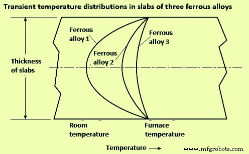
Fig 1 Effect of thermal conductivity on heat flow and internal temperature distribution
Solid materials which are heated in industrial furnaces are not necessarily continuous. Many times, the charge consists of coiled strip material or separate pieces piled to various depths or close side by side. In such cases, heat only can flow from one piece to the adjacent piece through small contact points on their surfaces, or through gas filled spaces, the thermal conductivity of which is very small. A stack of flat plates is an example of very low conductance. Even very small gaps constitute a big thermal resistance than solid metal. A stack cannot be treated as a solid, since thin air spaces are insulators. The differing air gaps in a stack result in bad non-uniformities in temperatures.
Rapid heat flow in each piece of a piled charge is obtained only by circulation of hot gases through the piled material by convection and gas radiation. These gas masses are to be constantly replaced with new hot gas since they have low mass, low specific heat, and thin gas beam thickness, so they cool quickly without delivering much heat to the loads. For uniform heating and precise reproducibility, piling of pieces of materials are to be avoided.
Heat transfer to the surface of the furnace charge – In furnace practice, heat is transferred by three modes namely (i) conduction, (ii) convection, and (iii) radiation. There are some essentials of heat transfer which are helpful to designers and operators of industrial furnaces. Most industrial furnaces, ovens, kilns, incinerators, boilers, and heaters use combustion of fuels as their heat source. Combustion, as used in industrial furnaces, comes from rapid and large chemical reaction kinetics and this result into conversion of chemical energy to sensible heat (thermal) energy. Increasing fuel and oxidizer (usually air) mixing surface area or increasing temperature of the reactants can cause faster combustion reactions, usually resulting in higher heat source temperatures. Fuel oxidation reactions are exothermic, so they can develop into a runaway condition (e.g. thermal energy being released faster than it can be carried away by heat transfer). This positive feedback can cause an explosion.
A flame is a thin region of rapid exothermic chemical reaction. An example is a Bunsen burner flame. In a Bunsen burner, a thoroughly premixed laminar stream of fuel gas and air is ignited by an external heat source, and a cone-shaped reaction zone (flame front) forms. Turbulence increases the thickness and surface area of the reaction zone, resulting in higher burning velocity. Laminar burning velocity for natural gas is around 18 metres per minute (mpm) while the turbulent burning velocity can be two to ten times faster. In a laminar flame, thermal expansion from chemical heat release can combine with increased reactivity caused by higher temperatures, resulting in acceleration to a turbulent flame. Except for long luminous flames, most industrial flames are turbulent.
Conduction heat transfer – Conduction heat transfer is molecule-to-molecule transfer of vibrating energy, usually within solids. Heat transfer solely by conduction to the charged load is rare in industrial furnaces. It occurs when cold metal is laid on a hot hearth. It also occurs, for a short time, when a piece of metal is submerged in a salt bath or a bath of liquid metal.
If two pieces of solid material are in thorough contact (not separated by a layer of scale, air, or other fluid), the contacting surfaces instantly assume an identical temperature somewhere between the temperatures of the contacting bodies. The temperature gradients within the contacting materials are inversely proportional to their conductivities (Fig 2).
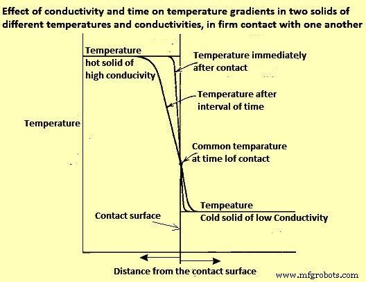
Fig 2 Effect of conductivity and time on temperature gradients in two solids of different temperatures and conductivities, in firm contact with one another
The heat flux (rate of heat flow per unit area) depends not only on the temperatures of the two solids but also on the diffusivities and configurations of the contacting solids. In practice, comparatively little heat is transferred to (or abstracted from) a charge by conduction, except in the flow of heat from a billet to water-cooled skids.
When a piece of cold metal is suddenly immersed in liquid salt, lead, zinc, or any other liquid metal, the liquid freezes on the surface of the cold metal, and heat is transferred by conduction only. After a very short time, the solid jacket, or frozen layer, remelts. From that time on, heat is transferred by conduction and convection.
Convection heat transfer
Convection heat transfer is a combination of conduction and fluid motion, physically carrying heated (or cooled) molecules to another surface. If a stream of gaseous fluid flows parallel to the surface of the solid, the vibrating molecules of the stream transfer some thermal energy to or from the solid surface.
A ‘boundary layer’ of stagnant, viscous, poorly conducting fluid tends to cling to the solid surface and acts as an insulating blanket, reducing heat flow. Heat is transferred through the stagnant layers by conduction. If the main stream fluid velocity is increased, it scrubs the insulating boundary layer thinner, increasing the convection heat transfer rate. The conductance of the boundary layer (film coefficient) is a function of mass velocity (momentum, Re number).
In furnaces which operate below 600 deg C, heat transfer by convection is of major importance since radiation is weak there. Modern high-velocity (high-momentum) burners give high convection heat transfer coefficients. High velocities often provide more uniform temperature distribution around a single piece charge, or among multiple piece charges, since more mass flow carries additional sensible heat at more moderate temperatures. At low furnace temperatures, high rates of total heat transfer can be obtained only by high gas velocities since heat transfer by radiation at around 550 deg C is less than one-tenth of what it is at around 1200 deg C. High-velocity (high momentum) burners are widely used to fill in where radiation cannot reach because of shadow problems.
Radiation heat transfer
Radiation between solids – Heat is radiated by solids even at low temperatures. The net radiant heat actually transferred to a receiver is the difference between radiant heat received from a source and the radiant heat re-emitted from the receiver to the source. The net radiant heat flux between a hot body (heat source) and a cooler body (heat receiver) can be calculated by Stefan-Boltzmann equations.
Emissivity and absorptivity of materials are important properties for radiation between solids. Emissivity is the radiant heat emitted (radiated) by a surface, expressed as a decimal of the highest possible (black body) heat emission in a unit time and from a unit area. Emittance is the apparent emissivity of the same material for a unit area of apparent surface which is actually much greater, due to roughness, grooving, and so on. Absorptivity is the radiant heat absorbed by a surface per unit time and unit area, expressed as a decimal of the most possible (black body) heat absorption.
Engineers use emissivity value of 0. 85 in conventional refractory lined furnaces. However, the temperature, surface condition, and alloy can make considerable difference. As an example, if stainless-steel strip is heated in less than three minutes in a catenary furnace, the emissivity may not change even though the temperature increases from ambient to 1100 deg C. By measuring both strip surface temperature and furnace temperature, it has been possible to revise heating curve calculations, assuming that oxidation has not changed the emissivity or absorptivity during the heating cycle.
Radiation from clear flames and gases – There are two origins of radiation from the products of combustion to solids. The two origins of radiation are (i) from clear flame and from gases, and (ii) from the micron-sized soot particles in luminous flame. Radiation from clear gas does not follow the Stefan-Boltzmann fourth-power law. The only clear gases which emit or absorb radiation appreciably are those having three or more atoms per molecule (triatomic gases) such as CO2, H2O, and SO2 (sulphur di-oxide). An exception is diatomic CO, which gives off less radiation. The other diatomic gases, such as O2, N2 (and their mixture, air), and H2 have only negligible radiating power.
Gaseous radiation does not follow the fourth-power law since gases do not radiate in all wavelengths, as do solids (gray bodies). Each gas radiates only in a few narrow bands. Radiation from clear gases depends on their temperature, on the partial pressure or percent volume of each triatomic gas present, and on the thickness of their gas layer.
The temperature of a radiating gas gets lower in the direction of gas travel. To maintain active gas radiation, the gas is to be continually replaced by new hot gas, which also improves convection. Higher gas feed velocities reduce the temperature drop along the gas path. This factor is very critical in maintaining good temperature uniformity in high temperature industrial furnaces.
The furnaces are often designed on the basis of refractory radiation heating the charge, with usually reasonable results, but some situations cannot be explained by refractory radiation alone. Direct radiation from furnace gases generally delivers 62 % (+/- 2 %) of the heat to the charge, and refractories transfer the remaining 38 % (+/- 2 %). Gas temperatures needed to transfer the heat to refractory and charge are generally much higher than generally assumed.
Radiation from luminous flames – If a fuel-rich portion of an air/fuel mixture is exposed to heat, as from a hotter part of the flame, the unburned fuel molecules polymerize or suffer thermal cracking, resulting in formation of some heavy, solid molecules. These soot particles glow when hot, providing luminosity, which boosts the flame’s total radiating ability.
If fuel and air are not thoroughly mixed promptly after they leave the burner nozzle, they can be heated to a temperature at which the hydrocarbons crack (polymerize). Further heating brings the resulting particles to a glowing temperature. As O2 mixes with them, they burn. As the flame proceeds, formation of new soot particles can equal the rate of combustion of previously formed particles. Farther along the flame length, soot production diminishes, and all remaining soot is incinerated. This series of delayed-mixing combustion processes are to be completed before the combustion gases pass into the flue. If the flame is still luminous at the flue entry, smoke can appear at the stack exit. Smoke is soot that has been cooled (chilled, quenched) below its minimum ignition temperature before being mixed with adequate air.
The added radiating capability of luminous flames causes them to naturally cool themselves faster than clear flames. This is performing their purpose—delivering heat. The cooling phenomenon can negate some of the gain from the higher luminosity (effective emissivity).
Luminous flames often have been chosen because the added length of the delayed mixing luminous flames can produce a more even temperature distribution throughout large combustion chambers. As industrial furnaces are supplied with very high combustion air preheat or more oxy-fuel firing, luminous flames can enable increases in heat release rates.
Fuels with high C/H2 ratios (most oils and solid fuels) are more likely to burn with luminous flames. Fuels with low C/H2 ratios (mostly gaseous fuels) can be made to burn with luminous flames namely (i) by delayed mixing, injecting equally low-velocity air and gas streams side-by-side, and (ii) by using high pressure to ‘shoot’ a high-velocity core of fuel through slower moving air so that the bulk of the air cannot ‘catch up’ with the fuel until after the fuel has been heated (and polymerized) by the thin ‘sleeve’ of flame annular interface between the two streams.
Flames from solid fuels can contain ash particles, which can glow, adding to the flame’s luminosity. With liquid and gaseous fuels, flame luminosity usually comes from glowing C and soot particles. The effective flame emissivity, as measured is usually between that of the POC gases and a maximum value of 0.95, depending on the total surface area of solid particles. Normally, heat transfer from a luminous flame is greater than that from a clear flame having the same temperature. The difference in the rate of heat transfer is quite noticeable in furnaces for reheating steel and metals. The difference becomes more pronounced at high temperature, where the radiating power of each triatomic gas molecule increases, but the gain is partially canceled by the decreasing density of radiating molecules per unit volume.
In another phenomenon, the bands of gaseous radiation hold their wavelengths regardless of temperature. At higher temperatures, however, the area of high intensity of solid radiation (glowing soot and C particles) moves toward shorter wavelengths (away from the gas bands). In higher temperature realms, radiation from clear gases does not increase as rapidly as radiation from luminous flames.
Flame radiation is a function of many variables such as C/H2 ratio of the fuel, air/fuel ratio, air and fuel temperatures, mixing and atomization of the fuel, and thickness of the flame. Some of these can change with distance from the burner. Fuels with higher C/H2 ratio, such as oils, tend to make more soot, so they usually create luminous flames, although blue flames are possible with light oils. Many gases have a low C/H2 ratio, and tend to burn clear or blue. It is difficult to burn tar without luminosity. It is equally difficult to produce a visible flame with blast furnace (BF) gas or with H2.
When comparing luminous and nonluminous flames, it is important to remember (i) soot radiation (luminous) usually ends where visible flame ends because soot is most often incinerated at the outer surface or skin of the flame, where it meets secondary or tertiary air, and (ii) gas radiation (nonluminous) occurs from both inside and outside the visible flame envelope, greatly increasing the uniformity and extent of its coverage, although gas radiation within the flame is somewhat shadowed by any surrounding soot particles or triatomic gases, and gas radiation outside the flame can be from cooler gases.
The effect of excess fuel on flame radiation is considerably greater than the effect of less excess air. The merits and demerits of clear flames versus long luminous flames have been debated for years. Modified burners and control schemes are helping to utilize the best of both. A problem common to several burner types is change of the flame characteristic as the burner input is turned down. Problems with some clear flame burners are (i) movement of the hump in the temperature profile closer to the burner wall as the firing rate is reduced, and (ii) at lower input rates, temperature falls off more steeply at greater distances from the burner wall (e.g., the temperature profile of a burner firing at 50 % of its rated capacity or below is at its peak temperature (maximum heat release at or near the burner wall, falling off further from the burner wall). At lower firing rates, the temperature drop off gets worse. At higher firing rates, the burner wall temperature decreases as the peak temperature moves away from it. In some steel reheating furnaces at maximum firing rate, the temperature difference between the burner wall and the peak can be 150 deg C.
The problem of a temperature peak at the far wall during high fire is aggravated by spur of furnace gases into the base of the flame, delaying mixing of fuel with O2. If the burner firing rate is increased, the spur of the products of complete combustion increases exponentially. Resulting problems are many. When side-firing a furnace at low firing rate, the peak temperature is at the burner wall, but at maximum firing rate, the peak temperature can be at the furnace centre or the opposite wall. Thus, the location of a single temperature control sensor is never correct. If the temperature sensor is in the burner wall, low firing rates have peak temperature hugging the furnace wall and driving the burner to low fire rate resulting into the rest of the furnace width receiving inadequate input. At high firing rates, a sensor in the burner wall is cool while the temperature away from the burner wall is very high, perhaps forming liquid scale on the surfaces of the charge pieces at the centre and/or far wall. To remedy this issue, inexperienced operators can lower the set point, reducing the furnace heating capacity.
Another example of the effect of the problem occurs with the bottom zone of a steel reheating furnace when fired longitudinally counter flow to the load movement, and with the control sensor installed 3 metre (m) to 6 m from the (end-fired) burner wall. At low-firing rates, with the zone temperature set at 1300 deg C, the burner wall can rise to higher than 1370 deg C. At that temperature, scale melts and drips to the floor of the bottom zone where it can later solidify as one big piece. At high firing rates, the peak temperature can move beyond the bottom zone T-sensor, possibly melting scale some distance toward the charge end of the furnace. Again, to avoid the problem, operators can lower temperature control settings, reducing the furnace capacity.
Control of the aforementioned problems requires an additional temperature sensor in each zone and a means for changing the mixing rate characteristic of the burner in response to the temperature measurements. Burners with adjustable spin (swirl) can be set to prevent much of the problem, especially if combined with a low-fire, forward-flow gas or air jet through the center of the burner. Such a jet is typically sized for 5 % of maximum gas or air flow.
Long, luminous flames, either laminar type or turbulent type, tend to have much less temperature hump and do not change length as rapidly when input is reduced. They can be great ‘levelers’, providing better temperature uniformity.
This information on in-flame soot radiation and triatomic gas radiation has been known for some time, but recent developments may be changing the picture. Use of oxy-fuel (100 % O2), both of which elevate flame turndown. The major gain from oxy-fuel firing is from more intense radiation heat transfer because of the higher concentration of triatomic gases, due to the elimination of N2 from the POC. This also decreases the mass of gas carrying heat out the flue (reducing stack loss). In another development, some lean premix gas flames (designed for low NOx emissions) make a ubiquitous flame field (seemingly transparent) through much of the chamber.
제조공정
유도로에서 철강 생산 중주파 코어리스 유도로는 일반적으로 저용량 철강 용해 공장에서 철강 생산에 사용됩니다. 유도로는 전원 공급 장치의 50Hz 주파수에서 필요한 중간 주파수를 생성하기 위한 변환기가 장착되어 있습니다. 이를 위해 정류기에서 직류 전압이 생성되고 평활 초크를 통해 인버터에 공급되고 보상 커패시터와 노 코일의 유도율을 통해 인버터에서 중간 주파수 전압이 생성됩니다. 변환기의 조절은 내장된 제어 전자 장치에 의해 수행됩니다. 퍼니스의 제어는 작동 캐비닛의 장치를 사용하고 필요한 경우 프로세서의 도움으로 수행됩니다.
고로 부담의 준비 및 충전 고로(BF)는 노로를 제외하고 기본적으로 BF에서 역류 방향으로 이동하는 가스 및 부하 입자의 통로입니다. BF의 안정적인 운전을 위한 기본 요건은 변동이 크지 않은 이동층을 로 내에서 유지하는 것입니다. 구체적으로, 혼합된 버디드 레이어가 없는 안정적인 가스 흐름과 버디드 레이어 구조를 형성하기 위함이다. 이들은 서로 밀접하게 관련되어 있습니다. 가스 흐름의 안정성은 거의 전적으로 부하 충진 구조(입자 크기, 입자 크기 분포 및 미세 입자 비율 등)에 의해 결정되는 부하 투과성과 고체 흐름인 부하 하