슈퍼커패시터는 에너지 저장장치의 하나로 초고정전용량, 높은 전력밀도, 긴 주기를 보인다. 슈퍼커패시터 재료에는 높은 비표면적, 기계적 및 화학적 안정성, 저렴한 비용이 요구되는 경우가 많습니다. 그래핀은 새롭게 떠오르는 탄소 재료로 그 고유한 특성 때문에 에너지 저장 분야에서 많은 주목을 받고 있다. 폴리머는 종종 슈퍼커패시터로서 여러 가지 향상된 또는 새로운 특성을 위해 그래핀에 통합됩니다. 이 논문에서는 슈퍼커패시터 애플리케이션을 위한 복합 재료를 형성하는 데 사용되는 다양한 폴리머를 검토합니다. 그래핀 및 고분자 복합재료의 기능, 전략 및 향상된 특성에 대해 논의합니다. 마지막으로 최근 개발된 플렉서블 슈퍼커패시터용 그래핀과 고분자에 대해서도 논의한다.
소개
2004년에 발견된 이래로 원자 1개 두께의 단일 탄소층인 그래핀은 오늘날 가장 많이 연구된 재료 중 하나입니다. 그래핀의 기본적인 특성은 전자, 역학, 광학 등과 같은 여러 응용 분야에서 매우 유망한 것으로 나타났습니다. 특히 그래핀 시트는 이론상 비표면적이 2630m
2
입니다. /g [1], 슈퍼커패시터 및 배터리를 포함한 에너지 저장 애플리케이션에 큰 관심을 불러일으켰습니다. 그래핀의 비표면적은 블랙 카본에 비해 훨씬 큽니다(일반적으로 <900m
2
/g) 및 탄소 나노튜브(100~1000m
2
) /g), 그러나 활성탄[2]과 유사합니다. 오늘날 슈퍼 커패시터 제조업체는 높은 비표면적, 저렴한 가격 및 대량 생산 능력 때문에 슈퍼 커패시터 전극의 활성 물질로 코코넛 껍질로 만든 활성탄을 주로 사용합니다. 슈퍼커패시터 애플리케이션에 사용되는 활성탄은 재, 할로겐, 철 및 기타 불순물을 1% 미만으로 줄이기 위해 정제하여 장치의 연장된 사이클링을 가능하게 하는 프리미엄 등급 탄소입니다. 시간이 지남에 따라 활성탄의 비용은 $150–200/kg에서 $15/kg으로 떨어졌으며 이 낮은 가격은 다른 탄소 재료가 시장에 진입하는 데 있어 강력한 장벽입니다[3]. 구리 또는 니켈 호일에 직접 화학 기상 증착(CVD)을 통해 성장한 그래핀 시트[4]는 품질이 가장 좋고 결함이 적습니다. 그러나 제조 비용이 너무 비싸고 확장성이 거의 없기 때문에 슈퍼커패시터 응용 분야에서 활성탄과 경쟁하는 것은 좋은 후보가 아닙니다. 오늘날 그래핀 기반 슈퍼커패시터에 대한 대부분의 연구는 그래핀 나노판, 그래핀 나노분말 및 그래핀 산화물, 환원 그래핀 산화물, 화학적 변형 그래핀 등과 같은 기타 그래핀 유도체에 초점을 맞추고 있습니다. 이러한 형태의 그래핀은 일반적으로 그래핀 나노시트의 이중 또는 다중 스택으로 구성됩니다. CVD 공정의 그래핀과 달리 이러한 형태의 그래핀은 상대적으로 저렴한 흑연의 화학적, 기계적 또는 열적 박리 공정에 의해 만들어집니다. 이러한 그래핀 유도체는 CVD 그래핀에 비해 표면 결함이 더 많아 트랜지스터, 광검출기, 대규모 투명 전도성 전극 등과 같은 고급 전자, 광전자/광전자 장치로 사용하는 데 방해가 될 수 있습니다. , 표면 결함의 증가된 밀도는 슈퍼커패시터 애플리케이션에 더 유리하고 종종 전기화학적 정전용량 능력의 증가로 이어진다[5]. 또한, 비용은 모든 실용적인 슈퍼 커패시터 장치에 대해 고려해야 할 가장 중요한 요소 중 하나입니다. 이 그래핀 나노판은 표면적이 커서 슈퍼커패시터 전극의 활물질로 많이 사용된다.
검토
그래핀 및 폴리머 바인더
그래핀 나노시트를 집전체에 결합하기 위해서는 고분자 바인더가 필요한 경우가 많다. 그 중 폴리불화비닐리덴(PVDF), 폴리테트라플루오로에틸렌(PTFE)과 같은 불소수지 중합체가 주로 사용된다.
그래핀 및 PVDF 슈퍼커패시터
PVDF는 높은 기계적 강도, 우수한 내화학성, 열적 안정성 및 우수한 내노화성을 나타내는 고비반응성 열가소성 불소수지입니다[6]. 화학, 반도체, 의료용 소재, 리튬 이온 배터리 등 다양한 응용 분야를 갖고 있다[6, 7]. 그래핀 기반 슈퍼커패시터의 경우, PVDF는 주로 전극 특성을 유지하고 기계적 강도를 제공할 뿐만 아니라 집전체에 그래핀 나노판 또는 나노 분말을 결합하기 위한 바인더 재료로 사용됩니다. 그래핀 기반 슈퍼커패시터 전극을 형성하기 위해 먼저 그래핀 나노판과 10~20wt%의 PVDF를 혼합한다. 좋은 혼합 결과를 얻으려면 일반적으로 PVDF와 그래핀 나노 혈소판을 반죽과 같은 페이스트 형태의 복합물로 만든 다음 N-Methyl-2-pyrrolidone(NMP) 또는 디메틸포름아미드(DMF)와 같은 유기 용매를 첨가하여 점도를 조정해야 합니다. 슬러리를 형성한다. 복합 슬러리를 집전체에 코팅한 후 건조 및 압축하여 슈퍼커패시터 전극을 형성한다. 닥터 블레이드 코팅, 바 코팅, 드롭 캐스트 등과 같은 여러 코팅 기술이 있습니다.
PVDF 함량이 충분하지 않으면 활성 그래핀과 집전체 사이에 충분한 결합 강도를 제공하지 못하고 접착 문제가 발생할 수 있으므로 PVDF 함량을 정밀하게 제어해야 합니다. 한편, PVDF 함량이 너무 많으면 슈퍼커패시터 전극의 전도도가 낮아져 슈퍼커패시터의 에너지 밀도와 전력 밀도가 감소한다. PVDF의 불리한 전도성 효과를 최소화하기 위해 카본 블랙(CB), 아세틸렌 블랙 등과 같은 전도성 탄소의 일정 비율을 혼합물에 도입할 수 있습니다. 전도성 탄소 나노입자는 (i) 그래핀 나노시트의 응집을 억제하는 충전재로 작용하고, (ii) 슈퍼커패시터 전극의 속도 용량 및 사이클 안정성을 개선하고, (iii) 전극의 높은 전기 전도도를 유지할 수 있다고 보고되었습니다. [8]. 이러한 전도성 탄소 재료는 일반적으로 크기가 20~50nm이며[9] 그래핀 재료에 고르게 분산됩니다. [9]에서 활물질은 환원그래핀 90%와 CB 10%로 이루어졌으며, 활물질은 PVDF와 95:5의 비율로 혼합된 후 니켈 폼 전극에 코팅되었다. CB의 추가는 환원된 그래핀/PVDF 전극의 전체 형태를 변경하지 않습니다. 175Fg
−1
의 특정 정전용량 환원된 그래핀/PVDF/CB 슈퍼커패시터 전극의 6000 주기 동안 9.1%의 정전용량 감소만이 [9]에서 얻어졌습니다.
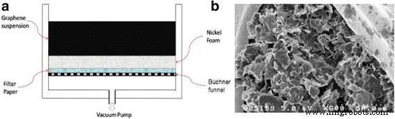
혼합 및 코팅 방법 외에도 진공 여과 방법을 사용하여 니켈 폼과 같은 다공성 집전체에 그래핀/고분자 슈퍼커패시터 전극을 형성할 수도 있습니다. 진공 여과의 개략도는 그림 1a에 나와 있습니다[10]. 그래핀의 양과 분포는 진공 압력과 공정 시간에 따라 조절될 수 있다. [10]에서는 활성 물질로 그래핀 나노판, 바인더 물질로 PVDF 25wt%, 전극으로 다공성 95% 니켈 폼을 사용했습니다. 진공 여과에 의해 형성된 증착된 그래핀 함유 전극의 SEM 이미지는 그림 1b에 나와 있습니다. 152Fg
−1
의 특정 정전용량 이 방법을 사용하여 2000주기 동안 95%의 정전 용량 유지가 보고되었습니다.
<그림>
아 그래핀을 포함하는 슈퍼커패시터 전극을 만들기 위한 진공여과 방법의 개략도. ㄴ 진공 여과에 의해 형성된 니켈 폼 상의 그래핀/PVDF의 SEM 이미지. [10]의 허가를 받아 재인쇄되었습니다. Copyright 2012 엘스비어
그래핀 및 PTFE 슈퍼커패시터
PTFE는 또한 일반적으로 사용되는 슈퍼 커패시터 폴리머 바인더이며 PVDF와 유사한 또 다른 유형의 플루오로 폴리머입니다. PVDF와 달리 백본에 더 많은 불소 원자가 있습니다. 또 다른 차이점은 물에 대한 용해도에 있습니다. PVDF는 일반적으로 백색 분말 형태이며 활성 물질(예:활성탄, 그래핀 및 탄소 나노튜브)과 혼합하기 위해 NMP와 같은 유기 용매가 필요합니다. 그러나 PTFE는 물에 분산될 수 있습니다(예:PTFE 60wt% 분산은 H2 O)[11,12,13], 이소프로판올[14,15], 에탄올[16,17,18]. 활성탄 슈퍼커패시터 산업은 이러한 특성 때문에 PTFE를 사용하는 경향이 있습니다. 유기용제 사용의 안전성 관련 문제는 말할 것도 없고 물용제를 처리하는 것이 비교적 비용 효율적이기 때문입니다.
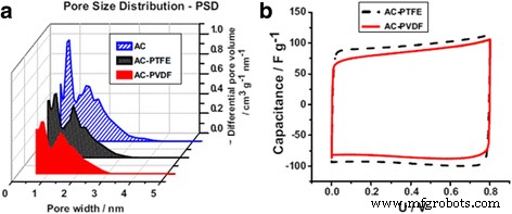
바인더의 유형이 다르면 슈퍼커패시터의 성능이 달라질 수 있습니다. Abbas et al. 활성탄(AC)의 경우 NaNO3를 사용하는 슈퍼커패시터 수성 전해질, 동일한 양(10wt%)의 다른 결합제(PTFE 대 PVDF)는 슈퍼커패시터의 전체 성능에 영향을 미칠 수 있습니다[19]. PVDF 바인더가 있는 전극은 그림 2a의 기공 크기 분포에서 볼 수 있듯이 PTFE 바인더가 있는 전극보다 다공성이 적은 것으로 나타났습니다. 결과적으로 AC-PTFE 전극은 그림 2b와 같이 AC-PVDF 전극에 비해 더 높은 미세다공성 부피(공극 폭 <5 nm)로 인해 더 높은 정전 용량을 달성합니다[19].
<그림>
아 AC, AC-PTFE 및 AC-PVDF 전극의 기공 크기 분포. ㄴ 순환 전압전류도(2mV · s
−1
) ) 1mol · L
-1
에서 최대 0.8V의 AC/AC 커패시터 PTFE 및 PVDF 바인더가 포함된 NaNO3. [19]의 허가를 받아 재인쇄되었습니다. Copyright 2014 엘스비어
PTFE는 절연성 및 소수성입니다. PTFE가 너무 많으면 전극의 전도도가 감소하고 수성 전해질 이온이 전극 재료의 미세 기공으로 침투하는 것을 억제하여 에너지 밀도와 비정전용량을 감소시킬 수 있습니다[20]. PTFE의 최적 함량은 활성 물질, 전극 물질 및 전해질 등을 포함한 여러 요인에 따라 다릅니다. Tsay et al. Na2를 사용하는 탄소 BP2000 기반 슈퍼커패시터의 경우 SO4 용액을 전해질로 사용하는 경우 복합재에 5wt%의 PTFE를 사용하여 최대 비정전용량 및 에너지 밀도를 달성합니다. PTFE 바인더가 충분하지 않으면 전극에서 활물질의 접착 문제가 발생할 수 있으며, 비정전용량, 특히 긴 주기에 걸친 정전용량 유지에도 부정적인 영향을 미칠 수 있습니다. 다른 연구에서 Zhu et al. 6M KOH 수성 전해질이 포함된 니켈 폼의 AC로 만들어진 슈퍼커패시터의 경우 10% PTFE에서 최대 비정전용량이 달성된다는 사실을 발견했습니다. 그러나 PVDF 바인더(5%)를 사용하는 경우 최적의 조건이 다릅니다[21].
우수한 습윤성은 전해질 이온이 전극 물질의 다공성 구조에 더 쉽게 접근할 수 있도록 하여 더 높은 이중층 정전 용량을 달성할 수 있습니다. 일부 수성 전해질에 대한 PTFE 바인더의 친수성을 증가시키기 위해 소량의 폴리비닐피롤리돈(PVP)(예:3%)을 PTFE 분산액에 첨가할 수 있습니다[22]. Paul et al. PTFE 바인더가 있는 전극 재료는 접촉각이 151°이며, 이는 본질적으로 초소수성을 나타냅니다. 그러나 3% PVP를 추가하면 접촉각이 22°로 급격히 감소하여 전극의 우수한 습윤성을 나타냅니다[23].
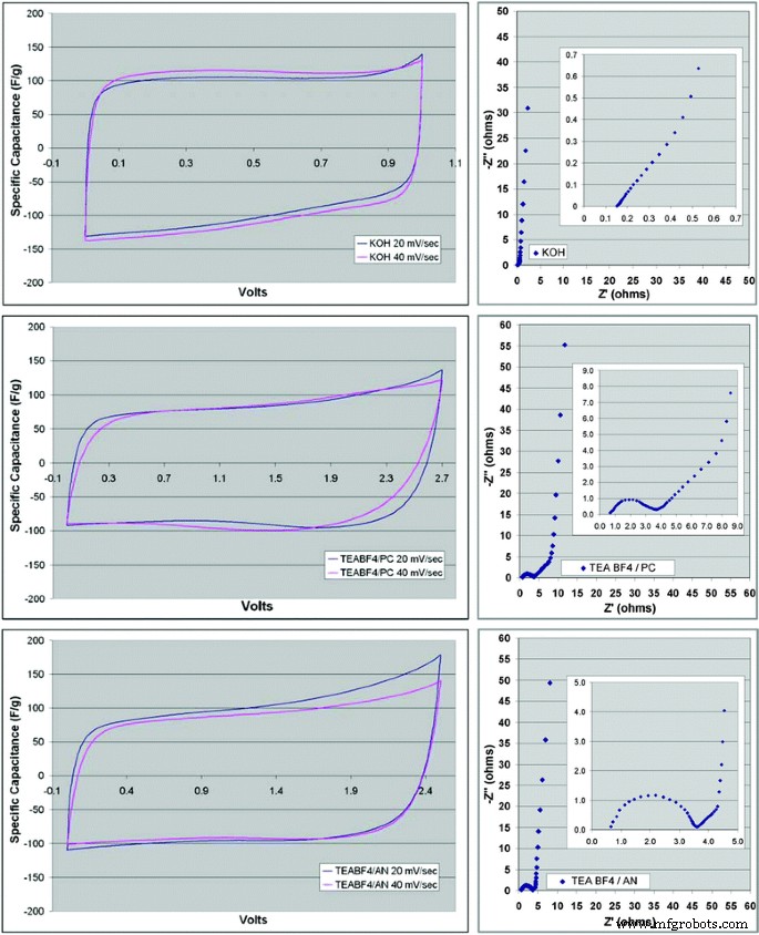
선택한 전해질에 따라 그래핀 기반 슈퍼커패시터는 다르게 작동할 수 있습니다. Stoller et al. 화학적으로 변형된 그래핀을 활성 물질로 사용하고 PTFE를 바인더로 사용하여 그래핀 기반 슈퍼커패시터를 형성하고 수성 및 유기 전해질 모두에서 테스트했습니다[24]. 그림 3은 KOH, TEABF4를 사용하는 그래핀/PTFE 슈퍼커패시터의 순환 전압전류법(CV) 및 Nyquist 플롯의 다양한 특성을 보여줍니다. 프로필렌 카보네이트(PC)에서, 그리고 다른 전해질로서 아세토니트릴(AN)에서 TEABF4. 수성 전해질 KOH는 116Fg
-1
의 가장 높은 비정전용량을 제공하는 것으로 밝혀졌습니다. 100Fg
−1
와 비교 TEABF4에서 /AN 및 95 Fg
−1
TEABF4/PC [24]에서. 또한 Nyquist 플롯에서 제안한 것처럼 슈퍼커패시터 셀의 등가 직렬 저항(ESR)이 세 전해질에서 다르다는 점에 유의해야 합니다. 슈퍼커패시터를 설계할 때 전해질과 활물질, 집전체의 상용성도 고려해야 한다.
<그림>
이력서(왼쪽 ) 및 Nyquist(오른쪽 ) KOH 전해질을 사용한 CMG 재료 플롯(상단 ), TEABF4 탄산 프로필렌(중간 ) 및 TEABF4 아세토니트릴(하단 ). [24]의 허가를 받아 재인쇄되었습니다. Copyright 2008 미국 화학 학회
그래핀 및 전도성 고분자 복합 재료
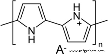
위에서 논의한 바와 같이 고분자 바인더는 슈퍼커패시터 전극을 형성하는 매우 중요한 부분이다. 그러나 폴리머 바인더 사용의 한 가지 단점은 일반적으로 전도성이 없고 슈퍼커패시터의 에너지 밀도를 감소시킬 수 있다는 것입니다. 그래핀/고분자 결합제 복합 재료 기반 슈퍼커패시터는 주로 EDL(전기 이중층) 커패시턴스를 기반으로 합니다. 반면에 전도성 고분자(CP)는 대안적인 접근 방식을 제공하며 슈퍼커패시터 응용 분야에서 많은 관심을 끌고 있습니다. 그것들은 전기적으로 전도되며 EDL 커패시턴스 외에 슈퍼커패시터에 저장된 의사 커패시턴스를 유발할 수 있는 전해질과 매우 빠른 산화환원 반응을 가질 수 있습니다. CP는 단일(C-C) 및 이중(C =C) 탄소 결합으로 구성된 π-공액 백본을 가지고 있습니다. 모든 공액 CP 중에서 폴리(피롤)(PPy), 폴리아닐린(PANI) 및 폴리(3,4-에틸렌디옥시티오펜)(PEDOT)은 높은 전도성, 용이성으로 인해 슈퍼커패시터 애플리케이션에서 가장 일반적으로 사용되는 세 가지 유형의 CP입니다. 합성, 비용 효율성 및 경량 [25, 26]. 이러한 중합체의 공액 골격은 산화에 의해 p-도핑되거나 환원에 의해 n-도핑되어 각각 p-형 CP 또는 n-형 CP를 형성할 수 있습니다. 그림 4는 p-도핑된 PPy의 화학 구조를 보여줍니다. 양전하는 PPy 메인 체인에서 비편재화되고 A
-
NO3와 같은 반대 음이온을 나타냅니다.
-
, ClO4
-
, Cl
−
등
<그림>
화학 구조 p-도핑된 PPy
높은 전도성, 빠른 충전 및 방전, 슈퍼커패시터 전극으로서의 높은 비정전용량에도 불구하고[27,28,29], 슈퍼커패시터 전극으로 CP만 사용할 때의 주요 단점은 긴 사이클 동안 안정성 문제가 발생한다는 것입니다. 긴 주기에 걸친 산화환원 반응 동안 CP의 체적 변화로 인한 기계적 응력은 균열, 재료 손실 또는 CP 파손으로 이어질 수 있습니다. 이러한 오류는 궁극적으로 시간이 지남에 따라 슈퍼커패시터 기기의 용량 저하 또는 고장을 유발할 수 있습니다. CP 기반 슈퍼커패시터의 수명을 늘리는 한 가지 솔루션은 CP를 여러 형태의 탄소(예:AC, CNT 및 그래핀)와 합성하는 것입니다. 이러한 복합 재료는 복합 재료의 탄소 네트워크가 충전 및 방전 주기 동안 체적 변화를 조정할 수 있으므로 더 나은 안정성을 보여 주기에 걸쳐 정전 용량 유지가 크게 향상될 수 있습니다[30,31,32]. 일반적으로 말해서, p-도핑된 CP는 n-도핑된 것보다 더 안정적입니다[33, 34]. 이 세션은 슈퍼커패시터 응용 분야에서 그래핀 및 그 유도체와 p-도핑된 CP의 합성물에 주로 초점을 맞출 것입니다.
그래핀 및 폴리아닐린(PANI) 합성물
PANI는 높은 전도성, 전기활성, 비정전용량 및 우수한 안정성으로 인해 슈퍼커패시터 전극 재료로 광범위하게 연구되었습니다. PANI는 전도와 적절하게 충전 및 방전되기 위해 양성자가 필요합니다. 따라서 PANI가 슈퍼커패시터 응용 분야에 사용되기 위해서는 양성자성 용매, 산성 용액 또는 양성자성 이온성 액체가 필요합니다[35, 36]. PANI의 가장 일반적인 합성 방법은 산화 중합과 전기화학적 중합이다. 계면 중합[37], 전기방사[38], 시딩 중합[39], 주형 중합[40] 등과 같은 다른 방법을 사용하여 나노구조의 PANI(예:나노섬유 및 나노입자)를 생성할 수도 있습니다. 각각의 방법으로 합성된 PANI 폴리머는 종종 다른 특성을 가지므로 결과적으로 생성된 PANI 기반 슈퍼커패시터는 다소 다른 성능을 나타낼 수 있습니다.
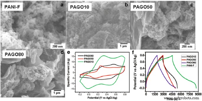
PANI와 그래핀의 합성물은 아닐린과 산성 용액의 그래핀 현탁액을 제자리 중합하여 제조할 수 있습니다. Zhang et al. 산화 그래핀(GO)을 사용하여 PANI와 혼합하여 합성물을 형성하고 전기화학적 특성화를 위해 유리질 탄소 작업 전극에 드롭 캐스트했습니다[41]. GO는 연구에서 수정된 Hummers 방법에 의해 흑연으로부터 제조되었으며 수십 마이크로미터 크기의 층형 구조를 가졌다. 산화 중합 방법은 1M 수성 HCl 산성 매질에서 PANI 나노섬유를 합성하기 위해 [41]에서 사용되었으며 암모늄 퍼옥시디설페이트((NH4 )2 S2 O8 )를 산화제로 사용하였다. 그림 5에서 볼 수 있듯이 GO/PANI 합성물의 다른 GO 농도는 합성물의 형태를 다르게 하여 슈퍼커패시터 전극으로서의 전기화학적 거동에 영향을 미칩니다[41]. 순수한 PANI 나노섬유는 CV 곡선에서 한 쌍의 산화환원 피크를 갖지만 GO/PANI 복합재는 두 쌍의 산화환원 피크를 나타내는 순수 GO 및 순수 PANI의 특성을 모두 나타냅니다. 순수 PANI 나노섬유(PANI-F) 전극은 420Fg
−1
의 매우 높은 비정전용량을 가집니다. 그러나 사이클링 안정성은 다소 낮고 비정전용량은 단 5 사이클 후에 거의 40% 감소합니다. GO 농도가 증가함에 따라 합성물의 비정전용량은 감소합니다(PAGO10:320Fg
−1
, PAGO50:207 Fg
−1
및 PAGO80:158 Fg
−1
). 반면에 복합 재료의 GO 농도가 높을수록 GO 나노 입자가 충전 및 방전 주기 동안 PANI의 체적 변화를 보상할 수 있기 때문에 긴 주기 동안 정전 용량 유지가 크게 향상됩니다.
<그림>
아 순수한 PANI 섬유(PANI-F)의 SEM. ㄴ GO 중량 백분율이 10%인 GO 및 PANI 복합 재료의 SEM(PAGO 10). ㄷ GO 중량 백분율이 50%(PAGO 50)인 GO 및 PANI 복합 재료의 SEM. d GO 중량 백분율이 80%(PAGO 80)인 GO 및 PANI 복합 재료의 SEM. 이 2M H2로 기록된 주기적 전압전류도 SO4 유리질 탄소 전극을 작업 전극으로, Pt 시트를 상대 전극으로, AgCl/Ag 전극을 기준 전극으로 코팅한 다양한 복합 재료를 사용하여. 스캔 속도는 100mV/s입니다. 에 0.1A/g의 전류 밀도에서 다양한 복합 전극의 충전/방전 사이클링 곡선. [41]의 허가를 받아 재인쇄되었습니다. Copyright 2010 미국 화학 학회
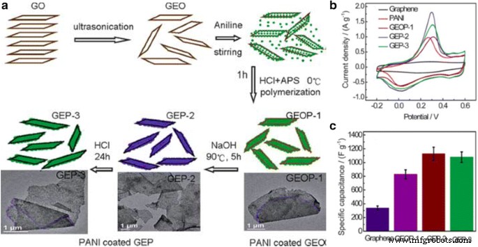
GO는 본질적으로 절연성이며 복합재의 GO 나노입자는 비정전용량에 거의 기여하지 않습니다. 합성물의 총 정전용량은 주로 PANI 나노섬유의 유사 정전용량에서 비롯됩니다. 많은 연구[42, 43]에서는 RGO가 더 높은 비정전용량을 갖고 더 높은 전도도로 인해 슈퍼커패시터 전극의 ESR을 감소시킬 수 있기 때문에 GO를 대체하기 위해 환원그래핀옥사이드(RGO)를 사용하기 시작했습니다. RGO 나노입자는 화학적, 열적 또는 전기화학적 방법을 기반으로 GO 나노입자를 환원시켜 제조할 수 있다. Wang et al. RGO 및 PANI 합성물을 형성하기 위해 in situ 중합-환원/탈도핑-재도핑 공정에 의한 3단계 합성 방법을 사용했습니다[44]. 이 현장 공정은 복합물에 RGO의 균일한 분산을 촉진할 수 있으며 그 개략도는 그림 6a에 나와 있습니다. (i) 에틸렌 글리콜의 GO를 초음파 처리하여 균일한 박리된 산화 그래핀 현탁액(GEO)을 얻습니다. (ii) 아닐린 용액을 교반하면서 혼합물에 첨가하고; (iii) 염산(HCl) 및 과황산암모늄(APS)이 중합을 위해 첨가되어 GO 및 PANI 복합물(GEOP-1)을 형성하고; (iv) 90°C에서 수산화나트륨(NaOH)을 현탁액에 첨가하여 GO를 환원하고 PANI 중합을 동시에 탈도핑하여 RGO 및 탈도핑된 PANI 복합재(GEP-2)를 형성합니다. (v) 마지막으로 HCl을 다시 도입하여 PANI를 다시 도핑하여 RGO와 다시 도핑된 PANI 합성물(GEP-3)을 형성합니다[44]. RGO 및 PANI 복합재료는 두께가 30~40nm이고 크기가 수 마이크로미터로 이러한 나노복합체의 특정 영역이 크다는 것을 의미합니다. 또한 그림 6b, c에서 GO를 RGO로 환원하면 PANI/RGO 전극의 산화환원 피크가 높아져 비정전용량이 높아진다는 것을 알 수 있습니다. 이 연구에서 가장 높은 비정전용량은 1129 Fg
−1
의 GEP-2입니다. . GO/PANI 복합 재료와 유사하게 RGO/PANI 슈퍼커패시터 전극의 사이클링 유지도 순수한 PANI 전극과 비교하여 개선되었습니다. GEP-2 및 GEP-3은 1000 사이클 후 각각 84 및 72%의 정전 용량 유지율을 갖습니다.
<그림>
아 그래핀/PANI 하이브리드 물질의 제조 과정을 보여주는 도식. ㄴ 1mV s
−1
에서 그래핀, PANI, GEOP-1, GEP-2, GEP-3의 CV 곡선 1백만 H2 후 SO4 -0.2 ~ 0.6V의 전위 범위에서. c 특정 커패시턴스는 샘플에 따라 달라집니다. [44]의 허가를 받아 재인쇄되었습니다. Copyright 2010 왕립화학학회
그래핀 및 폴리피롤(PPy) 합성물
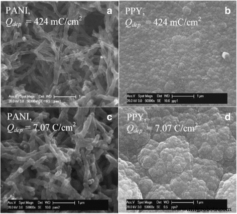
PPy는 Weiss et al.에 의해 처음 시연되었습니다. 1963년 [45]. PPy는 또한 이 폴리머의 합성이 간단하고 우수한 전도성과 열적 안정성을 모두 가지고 있기 때문에 슈퍼커패시터 애플리케이션을 위한 매우 매력적인 CP 재료입니다. 순수한 PPy 폴리머는 그림 7과 같이 PANI와 매우 다른 형태를 보입니다[46]. 얇은(그림 7a)와 두꺼운(그림 7c) PANI 필름은 모두 나노 피브릴로 구성됩니다. 그러나 서브미크론 입자를 포함하고 나중에 응집된 콜리플라워 유사 구조(그림 7d)를 형성하는 얇은 PPy 필름(그림 7b)은 중합 전하를 증가시켜 필름 두께를 증가시킵니다. 두꺼운 PPy 필름의 이러한 응집 구조는 표면적을 최소화하고 전해질 이온의 접근을 차단하는 경향이 있기 때문에 슈퍼 커패시터 응용 분야에 적합하지 않습니다. 또한 충전 및 방전 주기 동안 이러한 입자 구조는 체적 변화로 인한 응력으로 인해 쉽게 붕괴될 수 있습니다. 일반적으로 순수 PPy 필름은 PANI 필름에 비해 슈퍼커패시터로서의 사이클링 성능이 열등합니다[46].
<그림>
낮은 온도(424 mC/cm
2
)에서 표면 순수 PANI 및 PPy 필름의 SEM 이미지 ) 및 높음(7.07C/cm
2
) ) 보증금(Qdep ) 표시된 대로. [46]의 허가를 받아 재인쇄되었습니다. Copyright 2007 엘스비어
PANI/그래핀 나노복합체와 유사하게, 그래핀의 존재 하에 PPy의 제자리 중합도 바람직하다. 그렇게 함으로써 그래핀 나노입자의 더 나은 분산을 가질 수 있고 응집을 최소화할 수 있다. Bose et al. 그래핀 나노시트(GNS)의 응집을 피하기 위해 그래핀 표면을 수정하기 위해 폴리(나트륨 4-스티렌설포네이트)(Na-PSS) 존재하에서 GO를 감소시켰다[47]. GNS의 두께는 약 2nm이며 단일 그래핀 시트의 이중 또는 다중 레이어일 수 있습니다. 표면 개질된 GNS와 피롤 단량체를 에틸렌 용액에 혼합한 후, 염화 제2철(FeCl3 )을 혼합물에 첨가하여 중합을 시작하고 GNS/PPy 복합물이 형성됩니다. GNS/PPy 합성물의 성공적인 혼합은 라만 스펙트럼에서 순수한 GNS 및 PPy의 두 피크의 존재를 확인하여 나타낼 수 있습니다. [47]에서 GNS/PPy 복합재료는 순수 PPy 필름에 비해 슈퍼커패시터 전극보다 거의 2배의 비정전용량과 훨씬 더 나은 사이클링 성능을 갖는 것으로 관찰되었습니다. 다시 말하지만, 이러한 결과는 그래핀을 PPy에 통합하면 PPy의 전기화학적 활용을 촉진할 수 있고 PPy에 기계적 지원을 제공하여 충전 및 방전 주기 동안 복합 재료의 구조적 안정성을 향상시킬 수 있다는 증거를 제공했습니다.
그래핀 및 폴리(3,4-에틸렌디옥시티오펜)(PEDOT) 복합재
폴리(3,4-에틸렌디옥시티오펜)(PEDOT)은 1980년대 독일의 Bayer AG 연구소 과학자들에 의해 처음 개발되었습니다[48]. PEDOT은 표준 산화 화학 또는 전기화학적 중합 방법을 사용하여 제조할 수 있으며 도핑된 상태에서 몇 ~ 500S/cm의 매우 높은 전도도를 갖습니다[49, 50]. PEDOT은 처음에는 불용성으로 밝혀졌지만 나중에 수용성 고분자 전해질인 폴리(스티렌 설폰산)(PSS)을 사용하여 이 용해도 문제를 피할 수 있었습니다[51]. PEDOT은 또한 넓은 잠재 창, 우수한 열 및 화학적 안정성을 가지고 있어 슈퍼커패시터 커뮤니티에서 많은 관심을 받고 있습니다. 다른 전도성 고분자와 비교할 때 PEDOT은 70,000주기 동안 80%의 정전 용량 유지로 우수한 주기 안정성을 가지고 있습니다[52]. 그러나 슈퍼커패시터로서 PEDOT의 한 가지 단점은 분자량이 커서 비정전용량이 상대적으로 낮다는 것입니다[36].
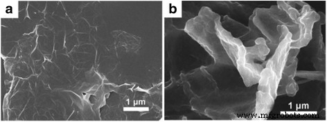
복합물에서 그래핀 나노입자의 응집을 최소화하기 위해 유사한 제자리 중합 방법을 사용하여 그래핀/PEDOT 복합물을 형성할 수 있습니다. 먼저 HCl[53], DI water[54, 55]와 같은 수용액에 PSS와 EDOT(ethylene dioxythiophene) 단량체를 혼합하고, 그래핀 또는 그래핀 유도체 나노입자를 분산시키기 전에 탈기 공정[55, 56]을 수행하기도 한다. 교반 또는 초음파 처리로 생성된 용액. 다음으로, 과산화이황산암모늄[(NH4 )2 S2 O8 )] 및 철(III) 염화물(FeCl3 ) [53], 또는 과황산나트륨(Na2 S2 O8 ) 및 황산철(III) [Fe2 (SO4 )3 ] [56] 그런 다음 중합을 시작하고 최종적으로 그래핀/PEDOT 복합물을 형성하기 위해 첨가됩니다. 그림 8은 RGO와 RGO/PEDOT 합성물의 SEM 이미지 비교를 보여줍니다[57]. 원래의 RGO 필름은 비교적 크고 매끄럽지만 RGO/PEDOT 복합 필름은 약 200nm 두께의 곡면 평면 필름을 형성했습니다[57]. 그래핀의 도입으로 그래핀/PEDOT의 전기 전도도는 원래의 PEDOT보다 2배 이상 향상되었으며 기계적 강도도 동시에 6배 향상된 것으로 보고되었습니다[58]. 복합 재료에서 그래핀의 역할은 전하 침투 및 전파 경로를 제공하여 PEDOT의 전반적인 전하 수송 거동을 개선하는 것입니다[59].
<그림>
(a의 SEM 이미지 ) 순수 RGO 필름(b ) RGO 및 PEDOT 복합 필름. [57]의 허가를 받아 재인쇄되었습니다. Copyright 2013 왕립화학학회
깨끗한 PEDOT 슈퍼커패시터는 70~130Fg
−1
범위의 특정 커패시턴스를 갖습니다. 다른 중합 방법에 따라 [52, 60, 61]. 그러나 그래핀/PEDOT 복합 재료 기반 슈퍼커패시터에서 향상된 비정전용량과 사이클링 안정성 성능이 모두 관찰되었습니다. 예를 들어, Alvi et al. 특정 정전용량이 304 및 261 Fg
−1
인 그래핀/PEDOT 기반 슈퍼커패시터 보고 HCl 및 H2 SO4 전해질, 각각 [53]. Wen et al. GO/PEDOT 복합 전극의 비정전용량이 136Fg
−1
라고 보고했습니다. , RGO/PEDOT 복합 전극의 비정전용량은 209Fg
−1
입니다. 2000주기 동안 87%의 정전용량 유지율을 제공합니다[62]. 복합재에서 슈퍼커패시터로서의 그래핀의 역할은 (i) PEDOT과 이질적인 구조를 형성하여 부피 변화(즉, 팽창, 및 수축) 충전-방전 주기 동안 PEDOT의 수축, (ii) 그래핀 또는 RGO는 PEDOT:PSS보다 더 높은 전기 전도도를 가지며, (iii) 그래핀을 추가하면 복합물이 전해질 침투 및 산화환원 반응을 위한 넓은 표면적을 제공하여 비정전용량을 크게 향상시킵니다[60].
그래핀 및 전도성 고분자(CP) 복합 재료 비교 및 요약
Graphene and its derivatives can have great influence on the morphologies, electrical properties, and the structural stabilities of the CPs when they are made into composites, and thus lead to drastic enhancement of the electrochemical properties of CPs. However, for a graphene/CPs supercapacitor, there are many factors which can determine the ultimate supercapacitor performance (i.e., specific capacitance, cycling stability, charge-discharge properties, etc.) such as polymerization method, intrinsic properties of individual CPs, electrolyte, dispersion/aggregation of the graphene in the composites, different properties of graphene used, etc. Generally speaking, for the aforementioned three types of CPs (PANI, PPy, and PEDOT), there are distinct advantages and disadvantages of using individual CPs to form the composite. PEDOT has the largest molecular molar mass, hence, the specific capacitance of the graphene/PEDOT composites supercapacitor is normally smaller than the ones formed with PANI or PPy. On the other hand, the larger particles formed in the PPy film make it less porous than PANI or PEDOT, thus the cycling performance of PPy is normally the worst among these three CPs. In addition, the conductivity comparison of these CPs is PEDOT > PPy > PANI [63], which can affect the ESR of the supercapacitors.
Zhang et al. compared the supercapacitor performance of the composites formed of RGO nanosheets with PANI, PPy, and PEDOT polymers using similar polymerization and mixing methods [42]. The specific capacitances of the supercapacitor electrodes from RGO/PANI, RGO/PPy, and RGO/PEDOT composites are 361, 249, and 108 Fg
−1
at the current density of 0.3 Ag
−1
, 각각. Figure 9a–c shows the different cyclic voltammograms (CV) of the RGO and CPs composite electrodes at different scan rates [42]. The quasi-rectangular CV curves of both RGO-PEDOT and RGO-PPy suggest good capacitive behaviors of both supercapacitor electrodes. The redox peaks in the range of +0.3 to 0 V on the RGO/PANI CV curves are due to the redox transition of PANI between the semiconducting state form and the conductive form [42, 64, 65]. Figure 9d shows the cycle stability of PANI fibers, RGO-PANI, RGO-PEDOT, and RGO-PPy during the long-term charge/discharge process [42]. With the RGO addition, all the composite supercapacitor electrodes showed good cycling performance compared to pristine PANI fibers with capacitance retention of only 68% after 600 cycles. However, RGO/PEDOT has the best capacitance retention of 88% after 1000 cycles, while RGO/PANI and RGO/PPy have the similar cycling performance of 82 and 81% retention after 1000 cycles [42].
Cyclic voltammograms of (a ) RGO-PEDOT (b ) RGO-PPy, and c RGO-PANi cycle stability of PANi fibers, RGO-PANi, RGO-PEDOT, and (d ) RGO-PPy during the long-term charge/discharge process. Reprinted with permission from [42]. Copyright 2012 American Chemical Society
Table 1 summarizes the recent development of graphene and CP (PANI, PPy, and PEDOT) composites in supercapacitor applications. Ragone plot comparing the power density and energy density of the graphene and CP composites supercapacitors in the summarized references is shown in Fig. 10. It should be noted that most studies reported specific capacitance of supercapacitor electrode based on three-electrode system (i.e., working, counter, and reference electrodes). Symmetric supercapacitor cells composed of anode and cathode of the same materials normally have less than half the specific capacitance of single electrode considering the separator and electrolyte weight. In addition, it is not surprising that very high specific capacitances in some studies were reported since only a small amount of active materials were applied/coated on the working electrode for electrochemical characterization. For practical purposes, it is hard to achieve the same level of specific capacitance since it may not increase linearly with increasing amount of materials.
Ragone plot of graphene and CP composites supercapacitors in the summarized references listed in Table 1
Graphene and Polymer Composites for Flexible Supercapacitor Applications
The recently developed flexible electronic devices such as flexible displays, curved smartphones, flexible implantable medical devices, and wearable electronic devices imply that flexible devices are beginning to emerge as the leading revolution in next generation of electronics. Several advantages of flexible electronic devices compared to conventional electronic devices include lighter weight, wearability, bendability, environmental friendliness, reduced cost, etc. In order to match the fast growth of flexible electronic devices, energy storage systems that are light, thin, and flexible should also be developed. Recently, considerable attempts have been made to develop flexible supercapacitor electrode based on carbon materials including activated carbon [7, 66], carbon nanofibers [67, 68], carbon nanotubes [69,70,71], and graphene [72,73,74,75]. Graphene film can be prepared ultrathin (<100 nm) by filtration method and transferred to a flexible polyethylene terephthalate (PET) substrate to make flexible supercapacitor electrodes as Fig. 11 shows [76]. Although the PET substrate is flexible and can provide mechanical support to the graphene film, it does not provide any capacitance as supercapacitors, thus the device capacity would be affected by introducing the additional PET substrate. In addition, there are issues associated with the transferring process, and it is hardly a scalable process as wrinkles or other defects can happen during the graphene transfer process. Furthermore, the restacking of graphene can cause the decrease of the surface area which leads to a relatively specific capacitance of 100 Fg
-1
for the 100-nm-thick graphene film. There are other types of flexible supercapacitor electrodes based on graphene materials, such as graphene paper [77, 78], graphene foam [79, 80], and graphene on carbon cloth/fabric [7, 81,82,83]. However, in each case, there may exist issues in graphene restacking, yield, limited power density and energy density, cost, and scalability. Similar to existing activated carbon supercapacitor industry, roll-to-roll manufacturing compatibility is an ideal feature for the flexible supercapacitor materials.
아 Photographs of transparent thin-films of varying thickness on glass slides. ㄴ TEM image of graphene collected from dispersion before filtration. ㄷ SEM image of 100 nm graphene film on glass slide. Reprinted with permission from [76]. Copyright 2012 AIP Publishing LLC
Graphene/conducting polymers (CPs) composite film, due to its flexible nature, becomes a viable option for flexible supercapacitor applications as it can also adapt to the roll-to-roll manufacture. Graphene/CPs film can be assembled with solid electrolyte to form a flexible supercapacitor device which can be subject to high degrees of bending or twisting without losing the device integrity. Meanwhile, as it is discussed previously, CP itself can provide pseudocapacitance due to the redox reaction, increasing the specific capacitance, as well as the capacity of the device. Figure 12 shows the schematics of a typical assembly process of a flexible supercapacitor using RGO-PEDOT/PSS film [84]. The PVDF substrate used in the coating process was later peeled off, which is a good way to eliminate the unnecessary weight and volume of the whole supercapacitor device. Poly(vinyl alcohol) (PVA)/H3 PO4 gel was used as the solid electrolyte in this device, and gold was sputter coated on one side of the electrode as the metal current collector [84]. Polymer gel electrolyte can be used as both a porous separator and electrolyte reservoir because of its microchannels or pores inside the structure, which facilitate the flow of electrolyte ions and avoid electrical shorting between the electrodes. Furthermore, the semi-solid framework of gel electrolyte provides good adhesion with minimal distance between the electrode/electrolyte/electrode interfaces, and thus efficiently enhances the charge-storage mechanism [85].
Schematic illustration of the preparation process of rGO-PEDOT/PSS films and the structure of assembled supercapacitor devices. Reprinted with permission from [84]. Copyright 2015 Nature Publishing Group
Bending test is usually necessary to examine the structural and electrical integrity of the flexible supercapacitor device subject to different bending angles and cycles. Bending or twisting can cause stress on the films which may lead to material loss, material fatigue (e.g., crack) or even material failure (e.g., fracture). CV and/or charge-discharge curves are monitored at several of bending angles during the bending cycles [84, 86,87,88,89,90] to test the device integrity. Graphene, due to its excellent mechanical strength, can prevent the flexible device from being ruptured by the repeatedly applied loads during the bending/twisting test, and it becomes an important part in the fabrication of the flexible electrode. Figure 13 shows the CV and specific capacitance of RGO-PEDOT/PSS flexible supercapacitor during the bending test [84], and it should be noted from Fig. 13b that there is no significant change of CV curves after 1000 bending cycles with a large bending angle (at 180 °). Figure 13c suggests that the specific capacitance of device in the 180 °bended state is only 5% smaller compared to the one under flat state after 10000 charge and discharge cycles. The flexible supercapacitor device made from a long strip of electrodes (15 × 2 cm) that have been rolled up as shown in Fig. 13d, e) was powerful enough to power a light-emitting diode for 20 s when fully charged (Fig. 13f) [84].
아 CVs of rGO-PEDOT/PSS during bending. Scan rate = 50 mV s
−1
. ㄴ CVs of rGO-PEDOT/PSS after being subject to bending. ㄷ Long-term test of rGO-PEDOT/PSS under flat or 180 ° bended states at a current density of 1 A g
−1
. d Flexible films coated with solid electrolyte spread out on an Au-coated membrane, e rolled design, and f the resulting device used to power a green light-emitting diode (LED). Reprinted with permission from [84]. Copyright 2015 Nature Publishing Group
Conclusions
The emergence of graphene has undoubtedly changed the scope of supercapacitor field due to its outstanding electrochemical properties along with other unique properties such as large surface area, high electrical conductivity, light weight, and mechanical strength. The recent development of graphene and polymer composites showed very promising features of these composite materials for supercapacitor applications. Compounded with binder polymers, graphene would compensate the undesired features of insulating polymers (e.g., insulating nature, low surface area, and low specific capacitance). On the other hand, when graphene makes composites with conducting polymers, it would provide mechanical support for the framework of the polymers and thus greatly improve the cycling performance as well as the specific capacitance. In addition, the flexible nature of the graphene/polymer film makes it possible for flexible, wearable, conformable energy storage devices. Despite the innovative ideas and techniques that have been demonstrated for the graphene/polymer supercapacitor device with unique features not possessed by current state-of-art technology, there remain a lot of challenges for graphene/polymer composite-based supercapacitors to reach their full potentials. One of the main challenges is to find a feasible way for the low-cost mass production of graphene/polymer supercapacitor electrode without compromising the micro/nanostructures of graphene due to the restacking or aggregation. Many studies have demonstrated the compatibility of large-scale coating or roll-to-roll manufacture capability of graphene/polymer supercapacitor electrodes, however, there is still a need to have a rational design of the porous structures inside the supercapacitor electrodes to form hierarchical interconnected porous microstructures and avoid the formation of dead volume or the collapse of the porous microstructures [91]. Furthermore, in most studies related to graphene/polymer-based supercapacitors, the mass specific capacitance of the supercapacitor electrode is often emphasized as one of the most important features. However, these values are often derived from the weight of a small amount of active material applied on the working electrode. In practical supercapacitor devices, to obtain a reasonable value of the device capacity, thicker coating or larger amount of material are often needed. It should be noted that the electrode total capacitance does not increase linearly with increasing amount of materials. In addition, one should also take into consideration the weight of current collector, electrolyte, and separator for supercapacitor device perspective. These aspects should be all considered to develop a deeper understanding of storage mechanism, interfacial relation, and designs of graphene/polymer-based supercapacitors. Last but not the least, integration of graphene/polymer supercapacitors with other electronic devices (e.g., solar cells, batteries) remains a challenge for practical applications. In conclusions, graphene/polymer composites have great potential for supercapacitor applications to improve current activated carbon-based supercapacitors, and we believe graphene/polymer-based supercapacitor would find its place in commercialization in the near future.