

제조공정

산업 제조
기술 프로세스의 프로세스 제어
기술 프로세스는 최종 제품을 수익성 있게 생산하기 위해 재료와 유체의 취급, 작업, 정제, 결합 및 조작으로 구성됩니다. 이러한 프로세스는 정확하고 까다로우며 잠재적으로 위험한 프로세스일 수 있습니다. 프로세스의 작은 변경이 최종 결과에 큰 영향을 미칠 수 있습니다. 최소한의 원료와 에너지로 원하는 품질의 최종 제품을 일관되게 생산하려면 비율, 온도, 흐름, 난류 및 기타 여러 매개변수의 변화를 신중하고 일관되게 제어해야 합니다.
일반적으로 작업을 지속적으로 모니터링해야 하는 모든 작업에는 프로세스 제어의 역할이 포함됩니다. 프로세스 제어는 기술 프로세스의 프로세스 변수를 제어하는 데 사용되는 방법을 말합니다. 프로세스가 지정된 한계 내에서 프로세스 작업을 실행하고 보다 정확한 한계를 설정하여 프로세스 효율성을 극대화하고 품질 및 안전을 보장할 수 있도록 하는 도구입니다.
모든 기술 프로세스는 정해진 작업을 성공적으로 수행하기 위해 많은 양의 계획이 필요합니다. 그러나 이러한 작업을 수행하기 위해 프로세스 운영자는 프로세스와 제어 시스템의 기능을 완전히 이해해야 합니다. 제어 시스템은 장비(측정 장치 및 제어 장치 등)와 작업자 개입으로 구성됩니다. 제어 시스템은 프로세스의 세 가지 기본 요구 사항, 즉 (i) 외부 교란의 영향 감소, (ii) 프로세스 안정성 촉진, (ii) 프로세스 성능 향상을 충족하는 데 사용됩니다.
계측은 기술 프로세스를 운영하는 데 사용되는 다양한 표시를 제공합니다. 어떤 경우에는 작업자가 프로세스 작업에 사용하기 위해 이러한 표시를 기록합니다. 기록된 정보는 작업자가 공정의 현재 상태를 평가하고 조건이 예상과 다를 경우 조치를 취하는 데 도움이 됩니다. 작업자가 필요한 모든 시정 조치를 취하도록 요구하는 것은 비현실적이거나 때로는 불가능하며, 특히 많은 수의 표시를 모니터링해야 하는 경우에는 더욱 그렇습니다. 이러한 이유로 대부분의 기술 프로세스는 정상 조건에서 작동하면 자동으로 제어됩니다. 자동 제어는 작업자의 부담을 크게 줄이고 작업을 관리하기 쉽게 만듭니다. 기술 프로세스는 (i) 변동성 감소, (ii) 효율성 증가, (iii) 안전 보장이라는 세 가지 이유로 제어됩니다.
공정 제어는 최종 제품의 변동성을 줄여 일관된 고품질 제품을 보장합니다. 공정 변동성이 감소하면 공정이 보다 안정적이고 신뢰할 수 있으며 생산적이며 경제적이 됩니다. 일부 공정 매개변수는 공정 효율성을 최대화하기 위해 특정 수준에서 유지되어야 합니다. 이러한 매개변수의 정확한 제어는 공정 효율성을 보장합니다. 또한, 공정 작동 중에 모든 공정 변수의 정밀한 제어가 유지되지 않으면 제어 불능 화학 반응과 같은 폭주 공정이 발생할 수 있습니다. 런 어웨이 프로세스의 결과는 치명적일 수 있습니다. 따라서 장비와 작업자의 안전을 확보하기 위해서는 공정의 정밀한 제어도 필요합니다.
공정 제어의 역할은 수년에 걸쳐 변화해 왔으며 기술에 의해 지속적으로 형성되고 있습니다. 프로세스 제어의 전통적인 역할은 프로세스 변수를 원하는 값에 가깝게 유지하여 안전에 기여하고 환경 영향을 최소화하며 프로세스를 최적화하는 것이었습니다. 과거에는 공정 매개변수의 모니터링이 공정 위치에서 수행되었고 매개변수는 작업자가 로컬로 유지 관리했습니다. 프로세스의 규모가 커지고 복잡해짐에 따라 프로세스 자동화의 역할이 점점 더 중요해졌습니다. 오늘날 자동화는 공정 제어 기능을 인수했으며, 이는 작업자가 현장의 기기와 통신하는 컴퓨터화된 분산 제어 시스템(DCS)의 도움을 받는다는 것을 의미합니다.
프로세스 제어는 프로세스 제어를 위한 메커니즘, 아키텍처 및 알고리즘을 다루는 통계 및 엔지니어링 분야의 혼합입니다. 효과적인 공정관리를 위해서는 공정기술에 대한 이해와 더불어 공정관리의 주요 개념과 일반용어에 대한 이해도 필요하다.
프로세스를 제어하는 이유는 원하는 방식으로 동작하도록 하기 위함입니다. 여기에는 프로세스가 더 정확하고, 더 안정적이거나, 더 경제적이 될 수 있습니다. 어떤 경우에는 제어되지 않는 프로세스가 불안정하고 손상되지 않도록 잘 제어해야 합니다. 따라서 우수한 제어는 응용 프로그램에 따라 다른 의미를 가질 수 있습니다.
공정 제어에서 기본 목적은 일부 매개변수의 값을 조절하는 것입니다. 조절한다는 것은 외부 영향에 관계없이 매개변수의 양을 원하는 값으로 유지하는 것을 의미합니다. 원하는 값을 기준값 또는 설정값이라고 합니다. 작업자는 설정값을 변경할 수 있습니다. 입력 설정값을 변경하여 입력 설정값과 일치하도록 출력이 변경되는 경우 프로세스가 자체 조절됩니다. .자가 조절 시스템은 특정 참조 값에 대한 변수 조절을 제공하지 않습니다. 매개변수는 입력 및 출력 값이 동일한 일부 값을 채택하고 그대로 유지됩니다. 그러나 입력유량을 바꾸면 출력도 바뀌므로 기준값으로 조절되지 않습니다.
운전자 보조 제어를 통해 운전자가 인위적으로 조절할 수 있습니다. 매개변수를 조절하여 필요한 값을 유지하기 위해서는 매개변수를 측정하는 센서가 필요합니다. 매개변수를 제어 변수라고 합니다. 적절한 제어 장비를 작동하여 작업자가 출력 매개변수를 설정값으로 변경할 수 있습니다. 출력 매개변수를 조작 변수 또는 제어 변수라고 합니다.
자동 제어 시스템은 제어 시스템을 대체하고 작업자의 작업을 대체하는 기계, 전자 또는 컴퓨터를 사용합니다. 매개변수의 값을 측정하고 이를 비례 신호로 변환할 수 있는 센서라는 장비가 추가되었습니다. 이 신호는 컨트롤러라고 하는 기계, 전자 회로 또는 컴퓨터에 대한 입력으로 제공됩니다. 컨트롤러는 측정을 평가하고 출력 신호를 제공하는 오퍼레이터의 기능을 수행합니다., 기계적 연결로 장비에 연결된 액추에이터를 통해 제어 장비 설정을 변경합니다. 일부 변수의 값을 설정값으로 조절하도록 설계된 시스템에 자동 제어가 적용될 때 이를 자동 프로세스 제어라고 합니다. 그림 1은 블록 다이어그램에서 입력 출력 변수를 보여주는 개념적 제어 프로세스를 보여줍니다.
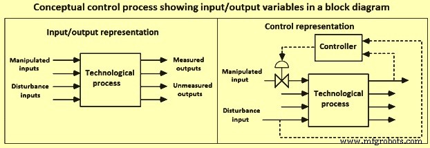
그림 1 블록 다이어그램에서 입력 출력 변수를 보여주는 개념적 제어 프로세스
기술 프로세스는 정상 상태에서 거의 작동하지 않기 때문에 본질적으로 동적입니다. 기술 프로세스의 작동은 작동이 안전하고 효율적이며 요구되는 속도로 지정된 품질의 원하는 제품을 생산할 수 있도록 지속적으로 발생하는 장애에 적절한 대응이 이루어지도록 하는 것으로 구성됩니다. 생산 방법은 공정마다 다르기 때문에 자동 제어의 원리는 본질적으로 일반적이며 공정의 크기와 유형에 관계없이 보편적으로 적용될 수 있습니다. 프로세스 제어 시스템의 목적은 다음 작업 중 하나 또는 둘 다를 수행하는 것입니다.
작업 조건 및 설정값에서 프로세스 유지 – 정상 상태 또는 비용, 수율, 안전 및 기타 품질 목표와 같은 모든 요구 사항을 충족하는 상태에서 작동하려면 많은 프로세스가 필요합니다. 많은 실제 상황에서 프로세스가 항상 정적 상태로 남아 있을 수는 없으며 프로세스를 불안정하게 만드는 프로세스에 방해가 발생합니다. 안정적이지 않은 프로세스에서 프로세스 변수는 제한된 시간 범위에 걸쳐 물리적 경계에서 진동합니다. 제어되지 않은 프로세스 변수는 자동으로 또는 작업자의 개입을 통해 제어 한계 내에서 프로세스 변수를 제어할 수 있는 제어 장비 및 장비를 추가하여 간단히 제어할 수 있습니다.
한 작업 조건에서 다른 작업 조건으로 프로세스 전환 – 실제 상황에서는 다양한 이유로 공정 작동 조건을 변경해야 하는 경우가 있습니다. 한 작동 조건 세트에서 다른 작동 조건 세트로 프로세스를 전환하는 이유는 경제성, 제품 사양, 작동 제약, 환경 규정 및 변경된 제품 사양 등으로 인한 것일 수 있습니다.
기술 프로세스에 대한 제어 전략의 개발은 다음을 공식화하거나 식별하는 것으로 구성됩니다. (iii) 측정된 변수 또는 측정되지 않은 변수일 수 있고 연속적으로 또는 불연속적인 시간 간격으로 측정될 수 있는 출력 변수, (iv) 하드 또는 소프트일 수 있는 제약, (v) 일괄 처리될 수 있는 작동 특성, 연속 또는 반 연속, (vi) 안전, 환경 및 경제적 고려 사항, (vii) 컨트롤러가 본질적으로 피드백 또는 피드백을 받을 수 있는 제어 구조. 기술 프로세스에 대한 프로세스 제어 시스템의 공식화는 7단계로 구성됩니다.
제어 시스템 개발의 첫 번째 단계는 제어 목표를 공식화하는 것입니다. 기술 프로세스는 일반적으로 여러 하위 프로세스로 구성됩니다. 각 하위 프로세스의 제어를 개별적으로 고려할 때 기술 프로세스의 제어가 감소합니다. 그럼에도 불구하고 각 하위 프로세스에는 여러 가지, 때로는 상충되는 목표가 있을 수 있으므로 제어 목표의 개발은 일반적으로 어려운 문제입니다.
두 번째 단계는 입력 변수의 결정을 구성합니다. 입력 변수는 주변 환경이 프로세스에 미치는 영향을 보여줍니다. 일반적으로 프로세스에 영향을 미치는 요소를 나타냅니다. 입력 변수는 조작 변수 또는 외란 변수로 분류할 수 있습니다. 조작된 입력은 제어 시스템(또는 프로세스 운영자)이 조정할 수 있는 입력입니다. 외란 입력은 프로세스 출력에 영향을 미치지만 제어 시스템에서 조정할 수 없는 변수입니다. 측정 가능한 방해 입력과 측정 불가능한 방해 입력이 모두 존재합니다. 입력은 지속적으로 또는 불연속적인 시간 간격으로 변경될 수 있습니다.
세 번째 단계는 출력 변수의 결정을 구성합니다. 출력 변수는 제어 변수라고도 합니다. 이는 주변 환경에 영향을 미치는 프로세스 출력인 변수입니다. 출력 변수는 측정된 변수와 측정되지 않은 변수로 분류할 수 있습니다. 측정은 연속적으로 또는 불연속적인 시간 간격으로 이루어질 수 있습니다.
네 번째 단계는 운영 제약 조건의 결정을 구성합니다. 모든 프로세스에는 특정 작동 제약 조건이 있습니다, 하드 또는 소프트로 분류됩니다. 엄격한 제약 조건의 예는 밸브가 완전히 닫힌 상태 또는 완전히 열린 상태의 극단 사이에서 작동하는 최소 또는 최대 유량입니다. 소프트 제약 조건의 예는 제품 구성이며 특정 제한 사이의 구성을 지정하는 것이 바람직하지만 안전이나 환경 위험을 제기하지 않고 이 사양을 위반할 수 있습니다.
다섯 번째 단계는 작동 특성의 결정을 구성합니다. 작동 특성은 일반적으로 배치, 연속 또는 반연속으로 분류됩니다. 연속 공정은 청소 및 정기 예방 유지 보수 등과 같은 특정 작업을 수행하기 위해 '종료'되기 전에 비교적 일정한 작동 조건에서 장기간 작동합니다. 배치 공정은 본질적으로 동적입니다. 즉, 일반적으로 짧은 시간 동안 작동합니다. 기간 및 작동 조건은 해당 기간 동안 상당히 다를 수 있습니다. 배치 공정의 예는 제강로에서 열을 만드는 것입니다. 회분식 반응기의 경우 반응기에 초기 충전이 이루어지며 회분식 공정이 끝날 때 원하는 제품을 생산하기 위해 공정 조건이 변경됩니다. 전형적인 반연속 공정은 반응기에 초기 충전물을 가질 수 있지만 배치 실행 과정에서 공급 성분을 반응기에 추가할 수 있습니다. 연속 주조 공정은 반연속 공정의 예입니다. 중요한 고려 사항은 프로세스의 지배적인 시간 척도입니다. 연속 공정의 경우 이는 반응기 내 물질의 체류 시간과 매우 관련이 있습니다.
여섯 번째 단계는 안전, 환경 및 경제적 문제에 관한 중요한 고려 사항을 구성합니다. 어떤 의미에서는 안전하지 않거나 환경적으로 위험한 프로세스가 규제 처벌과 비효율성으로 인해 운영 비용이 더 많이 들기 때문에 경제성이 궁극적인 원동력입니다. 또한 사양에 맞는 제품을 생산하면서 에너지 비용을 최소화하는 것이 중요합니다. 더 나은 프로세스 자동화 및 제어를 통해 프로세스는 '최적' 조건에 더 가깝게 작동하고 가변성 사양이 충족되는 제품을 생산할 수 있습니다.
'안전한' 개념은 기기 선택에서 항상 중요합니다. 예를 들어, 제어 밸브는 밸브 스템을 움직이고 흐름을 변경하기 위해 에너지원이 필요합니다. 대부분 공압 신호입니다(보통 3 -15 PSI). 신호가 손실되면 밸브 스템은 3 PSI 한계로 이동합니다. 밸브가 'Air-to-Open'인 경우 기기 공기의 손실로 인해 밸브가 닫히며 이를 '페일클로즈' 밸브라고 합니다. 반면에 밸브가 닫힐 공기인 경우 기기의 공기가 손실되면 밸브가 완전히 열린 상태가 되며 이를 '페일오픈' 밸브라고 합니다.
(i) 피드백 제어 및 (ii) 피드백 제어의 두 가지 표준 제어 유형이 있습니다. 피드포워드 컨트롤러는 교란 변수를 측정하고 이 값을 컨트롤러에 전송하여 조작된 변수를 조정합니다. 피드백 제어의 목적은 제어 변수를 설정값에 가깝게 유지하는 것입니다. 피드백 제어 시스템은 출력 변수를 측정하고 값을 원하는 출력 값과 비교하고 이 정보를 사용하여 조작된 변수를 조정합니다. 피드백 컨트롤러는 설계상 편차를 줄이기 위해 수정 조치를 취합니다. 피드백 컨트롤러는 제어 변수가 원하는 설정값에서 벗어나 0이 아닌 오류를 생성한 후에만 조치를 취할 수 있습니다. 그러나 프로세스 또는 측정이 매우 느리게 변경되는 경우 방해에 대한 응답이 매우 느릴 수 있습니다. 이러한 상황에서 피드포워드 컨트롤러는 성능을 향상시킬 수 있습니다. 피드포워드 컨트롤러는 교란이 제어 변수에 미치는 영향을 예측하고 교란의 영향을 상쇄하는 제어 조치를 취합니다.
프로세스에 대한 피드백 제어 구조를 결정하는 것은 측정된 변수를 제어하기 위해 어떤 조작 변수를 조정할 것인지 결정하는 것으로 구성됩니다. 측정된 프로세스 출력의 원하는 값을 설정값이라고 합니다. 제어 변수가 설정값에서 벗어나는 데에는 두 가지 이유가 있습니다. 설정값은 더 나은 성능을 달성하기 위해 의도적으로 변경되거나 방해로 인해 원하는 설정값에서 멀어집니다. 교란을 거부하도록 설계된 컨트롤러를 레귤레이터라고 하며 설정값 변경을 추적하도록 설계된 컨트롤러를 서보 메커니즘이라고 합니다. 일반적으로 연속 프로세스의 경우 설정값 변경은 드물게 발생하며 일반적으로 감독 컨트롤러가 더 유리한 작동 지점을 계산하는 경우에만 발생합니다. 따라서 레귤레이터가 사용되는 피드백 컨트롤러의 가장 일반적인 형태입니다. 대조적으로 서보 문제에 대한 컨트롤러는 설정값의 빈번한 변경이 발생하는 배치 프로세스에서 일반적입니다.
제어 시스템 설계에 사용되는 특히 중요한 개념은 '공정 이득'입니다. '프로세스 이득'은 프로세스 입력의 변화에 대한 프로세스 출력의 민감도입니다. 프로세스 입력의 증가가 프로세스 출력의 증가로 이어지는 경우 이를 양의 이득이라고 합니다. 반면에 프로세스 입력이 증가하면 프로세스 출력이 감소하는 경우 이를 음의 이득이라고 합니다. '프로세스 이득'의 크기도 중요합니다.
제어 구조가 결정되면 제어 알고리즘을 결정하는 것이 중요합니다. 제어 알고리즘은 측정된 출력 변수 값(원하는 출력 값과 함께)을 사용하여 조작된 입력 변수를 변경합니다. 제어 알고리즘에는 허용 가능한 성능을 갖도록 조정되어야 하는 여러 제어 매개변수가 있습니다. 종종 실제 프로세스에서 제어 전략을 구현하기 전에 시뮬레이션 모델에서 조정이 수행됩니다. 모델 기반 제어의 경우 컨트롤러에는 프로세스의 모델이 '내장'되어 있습니다.
단일 조작 변수와 단일 제어 변수(그림 2)가 있는 기술 프로세스의 블록 다이어그램에는 피드포워드, 피드백 및 감독 제어가 포함됩니다. 피드백 컨트롤러의 주요 목적은 일부 기기에 의해 측정되는 제어 변수 X를 원하는 설정점 Xsp에 가능한 한 가깝게 유지하는 것입니다. 제어 변수는 기술 프로세스의 모든 매개변수가 될 수 있습니다. 설정값은 일반적으로 실시간 수치 최적화 기술을 사용하는 감독 제어 시스템에 의해 결정됩니다. 최종 제어 요소에는 여러 유형이 있습니다. 부하 변수라고도 하는 외란 변수 D는 제어 변수가 설정값에서 벗어나게 하여 원하는 작동 지점으로 되돌리기 위해 제어 조치를 요구할 수 있습니다. 피드백 및 피드백 제어는 모두 교란의 영향을 줄일 수 있으며 각 방법에는 고유한 장점과 단점이 있습니다. 외란은 외부 환경 변수를 비롯한 다양한 원인으로 인해 발생할 수 있습니다. 어떤 경우에도 외란 변수는 프로세스 컨트롤러의 영향을 받을 수 없습니다. 제어 변수 X와 설정값 Xsp 사이의 오류 또는 편차 E는 피드백 컨트롤러에 대한 입력이며, 오류를 줄이기 위해 조작된 변수 M을 변경합니다. 일반적인 기술 프로세스에는 이러한 제어 루프가 많이 있을 수 있습니다.
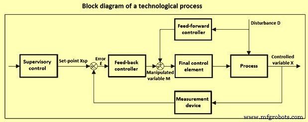
그림 2 기술 프로세스 제어를 위한 블록 다이어그램
하드웨어 및 소프트웨어 제어
공정 산업에서 실행되는 공정 제어는 1940년대에 처음 도입된 이후 상당한 변화를 겪었습니다. 1960년대 초에 전기 아날로그 제어 하드웨어는 공압 아날로그 제어 하드웨어의 대부분을 대체했습니다. 그러나 많은 공정에서 특정 제어 요소, 즉 제어 밸브 액추에이터는 오늘날에도 여전히 공압 상태로 남아 있습니다. 1960년대의 전기 아날로그 컨트롤러는 각 입력이 프로세스의 측정 지점에서 대부분의 컨트롤러가 위치한 제어실로 먼저 전달되는 단일 루프 컨트롤러였습니다. 그런 다음 컨트롤러의 출력이 제어실에서 최종 제어 요소로 전송되었습니다. 작업자 인터페이스는 단일 루프 컨트롤러 및 표시기를 위한 디스플레이 전면판과 차트 기록기가 결합된 제어판으로 구성되었습니다. 제어 전략은 일반적으로 비례 적분(PI) 컨트롤러를 사용하는 피드백 제어와 주로 관련되었습니다. 1950년대 후반과 1960년대 초반에 DDC(직접 디지털 제어) 및 감독 프로세스 제어를 수행하는 프로세스 제어 컴퓨터가 도입되었습니다. DDC를 사용하는 경우 DDC 루프는 종종 100%에 가까운 아날로그 제어 백업을 가지므로 시스템 비용이 많이 듭니다.
다른 초기 시스템은 주로 감독 프로세스 제어를 위해 프로세스 제어 컴퓨터를 사용했습니다. 규제 제어는 백업이 필요하지 않은 아날로그 컨트롤러에 의해 제공되었지만 운영자의 관심은 제어판과 컴퓨터 화면 사이에 분산되었습니다. 감독 제어가 사용 중일 때는 터미널 디스플레이가 운영자 인터페이스를 제공했지만 아날로그 백업이 필요한 시간에는 제어 패널이 여전히 제어실에 있었습니다. 이 환경 내에서 피드포워드 제어, 다변수 디커플링 제어 및 캐스케이드 제어와 같은 고급 제어 기술이 광범위하게 사용되었습니다. 이러한 초기 제어 시스템의 기능은 프로세스 특성보다는 컴퓨터의 기능을 중심으로 설계되었습니다. 부적절한 작업자 교육 및 비우호적인 사용자 인터페이스와 함께 이러한 제한 사항은 작동, 유지 관리 및 확장이 어려운 설계로 이어졌습니다. 또한 많은 다른 시스템이 사양을 맞춤화하여 매우 비쌌습니다. 공정 산업에 디지털 시스템 응용 프로그램이 도입된 것은 저렴한 마이크로프로세서가 상용화된 1970년 무렵이었습니다.
분산 제어 시스템(DCS) – DCS는 그림 3과 같이 많은 요소로 구성됩니다. 호스트 컴퓨터는 최적화 및 고급 제어 전략과 같은 계산 집약적인 작업을 수행합니다. 디지털 전송 링크로 구성된 데이터 고속도로는 시스템의 모든 구성 요소를 연결합니다. 중복 데이터 하이웨이는 데이터 손실 가능성을 줄입니다. 운영자 제어 스테이션은 프로세스를 감독하고 제어하기 위해 시스템과 운영자 통신을 위한 비디오 콘솔을 제공합니다. 많은 제어 스테이션에는 알람 로깅, 보고서 인쇄 또는 프로세스 그래픽의 하드 복사를 위한 프린터가 있습니다. 원격 제어 장치는 PID 알고리즘과 같은 기본 제어 기능을 구현하고 때때로 데이터 수집 기능을 제공합니다. 프로그래머 콘솔은 분산 제어 시스템을 위한 응용 프로그램을 개발합니다. 대용량 저장 장치는 제어 목적과 기업 결정을 위해 프로세스 데이터를 저장합니다. 저장 장치는 하드 디스크 또는 데이터베이스 형태일 수 있습니다. 컨트롤러, 입력 및 출력 간의 통신 및 상호 작용은 배선이 아닌 소프트웨어로 구현됩니다. 따라서 DCS는 제어실의 외관에서 고급 제어 전략의 광범위한 사용에 이르기까지 공정 제어의 많은 측면에 혁명을 일으켰습니다.
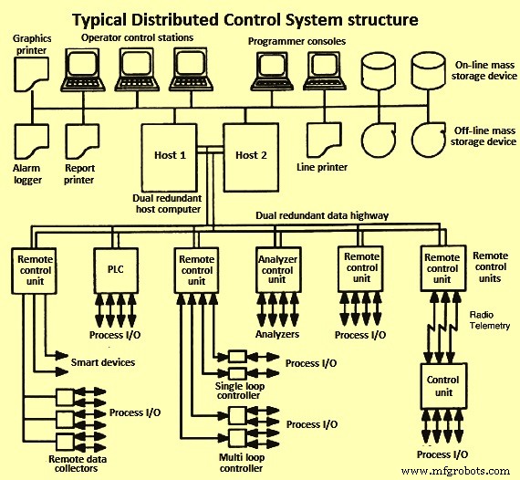
그림 3 DCS 시스템의 일반적인 구조
프로그래머블 로직 컨트롤러(PLC) – 처음에 PLC 컨트롤러는 시퀀싱 및 인터록을 위한 간단한 이진 논리를 실행하는 전용 독립형 마이크로프로세서 기반 장치였습니다. PLC는 그러한 로직에 대한 수정 및 변경이 구현될 수 있는 용이성을 크게 향상시켰습니다. PLC는 계산 기능 면에서 점점 더 강력해졌습니다. 일괄 처리 제어는 로직 유형 제어에 의해 지배되며 PLC는 DCS에 대한 선호되는 대안입니다. DCS와 PLC 간의 비교적 원활한 통합 인터페이스의 가용성으로 인해 현재 관행은 일반적으로 DCS와 PLC의 통합 조합을 사용하는 것입니다. 대부분의 PLC는 또한 순차 논리를 처리하며 미리 정해진 시간만큼 동작을 지연시키고 미리 정해진 시간 동안 동작을 실행하는 등의 내부 타이밍 기능을 갖추고 있습니다.
안전 및 차단 시스템 – 프로세스 제어는 프로세스의 안전 고려 사항에서 중요한 역할을 합니다. 자동화된 절차가 일상적인 작업을 위한 수동 절차를 대체하면 위험한 상황으로 이어지는 인적 오류의 가능성이 줄어듭니다. 또한 현재 플랜트 상태에 대한 작업자의 인식이 향상됩니다. 위험한 전자 프로세스에 대한 보호 시스템이 제공되어야 합니다. 한 가지 방법은 프로세스를 이러한 조건이 존재할 수 없는 상태로 만드는 특정 목적을 위한 논리를 제공하는 것입니다. 이를 안전 인터록 시스템이라고 합니다. 공정 제어 시스템과 안전 인터록 시스템은 다른 용도로 사용되기 때문에 물리적으로 분리되어야 합니다. 이는 의도하지 않은 안전 시스템 변경의 위험을 줄입니다. 3중 모듈식 이중화 시스템과 같은 안전 차단을 위해 특수 고신뢰성 시스템이 개발되었습니다. 이렇게 하면 시스템에 내부 오류가 발생하고 기본 기능을 계속 수행할 수 있습니다. 기본적으로 트리플 모듈식 이중화 시스템은 동일한 기능을 동시에 수행하는 3개의 동일한 하위 시스템으로 구성됩니다.
알람 – 경보의 목적은 즉각적인 주의가 필요한 공정 조건에 대해 공정 운영자에게 경고하는 것입니다. 비정상 상태가 감지되고 경보가 발행될 때마다 경보가 활성화됩니다. 비정상 상태가 더 이상 존재하지 않으면 알람이 정상으로 돌아갑니다. 알람은 측정된 변수, 계산된 변수 및 컨트롤러 출력에 대해 정의할 수 있습니다. 다양한 종류의 알람이 존재합니다.
스마트 트랜스미터, 밸브 및 필드 버스 – 디지털 기술의 사용 증가를 향한 공정 제어 기술의 경향이 명확하게 정의되어 있습니다. 디지털 통신은 필드 버스, 즉 동축 또는 광섬유 케이블을 통해 발생하며 지능형 장치가 직접 연결되어 제어실 또는 원격 장비실과 디지털 신호로 전송됩니다. 필드 버스 접근 방식은 트위스트 페어 및 관련 배선의 필요성을 줄입니다(그림 4).
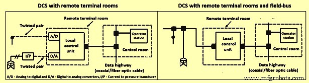
원격 룸 터미널 및 필드 버스가 있는 그림 4 DCS
다양한 필드 네트워크 프로토콜은 필드 장치, 기기 및 제어 시스템 간에 디지털 정보 및 지침을 전송하는 기능을 제공합니다. 필드 버스 소프트웨어는 구성 요소 간의 정보 흐름을 중재합니다. 디지털 통신 라인을 통해 여러 디지털 장치를 연결하고 서로 통신할 수 있으므로 배선이 크게 줄어듭니다.
공정 제어 소프트웨어 – 가장 널리 채택된 사용자 친화적인 접근 방식은 양식 채우기 또는 테이블 기반 PCL(프로세스 제어 언어)입니다. 인기 있는 PCL에는 기능 블록 다이어그램, 래더 논리 및 프로그래밍 가능한 논리가 포함됩니다. 이러한 언어의 핵심은 아날로그 입력, 디지털 입력, 아날로그 출력, 디지털 출력 및 PID 등과 같은 여러 기본 기능 블록 또는 소프트웨어 모듈입니다. 일반적으로 각 모듈에는 하나 이상의 입력과 출력이 포함됩니다. 프로그래밍에는 그래픽 사용자 인터페이스를 통해 블록의 출력을 다른 블록의 입력으로 교환하는 작업이 포함됩니다. 사용자는 입력 값의 소스, 출력 값의 대상 및 모듈을 위해 준비된 양식/테이블의 매개변수를 나타내는 템플릿을 작성해야 합니다. 소스 및 대상 공백은 적절한 경우 프로세스 I/O(입력/출력) 채널 및 태그 이름을 지정할 수 있습니다. 모듈을 연결하기 위해 일부 시스템에서는 데이터를 생성하거나 수신하는 모듈의 태그 이름을 채워야 합니다. 사용자 지정 필드에는 특수 기능, 선택기(최소 또는 최대), 비교기(이하) 및 타이머(활성화 지연)가 포함됩니다. 대부분의 DCS는 기능 블록 생성을 허용합니다.
시설 관리 계층 – 다양한 최적화, 제어, 모니터링 및 데이터 수집 활동이 사용되는 기술 프로세스의 5가지 수준은 그림 5에 나와 있습니다. 그림에서 각 블록의 상대적 위치는 개념적입니다. 수행된 기능. 각 레벨이 활성화된 상대적인 시간 척도도 표시됩니다. 5가지 개념적 제어 수준 각각에는 하드웨어, 소프트웨어, 기술 및 사용자 지정 측면에서 고유한 요구 사항과 요구 사항이 있습니다. 정보는 계층 구조에서 위로 흐르고 제어 결정은 아래로 흐르기 때문에 특정 수준에서 효과적인 제어는 우려 수준 아래의 모든 수준이 제대로 작동하는 경우에만 발생합니다. 최고 수준(계획 및 일정 수립)은 공급 및 물류 제약을 충족하기 위해 생산 목표를 설정하고 시간에 따라 변하는 용량 및 인력 활용 결정을 처리합니다. 이것을 ERP(전사적 자원 관리)라고 합니다.
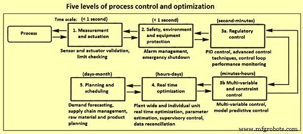
그림 5 프로세스 제어 및 최적화의 5단계
일반적으로 다양한 수준의 제어 응용 프로그램은 다음 목표 중 하나 이상을 목표로 합니다. ) 운영자의 주의와 개입의 필요성을 최소화하고 (iv) 혼란과 방해의 수, 범위 및 전파를 최소화합니다.
계측기 – 제어 똥의 구성 요소로 구성됩니다. 프로세스와 제어 계층 간의 직접적인 인터페이스를 제공하는 계측은 프로세스 상태에 대한 정보의 기본 소스이자 시정 조치가 프로세스에 전송되는 궁극적인 수단으로 사용됩니다. 공정 측정 장치의 기능은 공정 변수의 값 또는 값의 변화를 감지하는 것입니다. 실제 감지 장치는 물리적 움직임, 압력 신호 및 밀리볼트 신호 등을 생성할 수 있습니다. 변환기는 측정 신호를 물리적 또는 화학적 양에서 다른 것으로(예:압력에서 밀리암페어로) 변환합니다. 변환된 신호는 전송 라인을 통해 제어실로 전송됩니다. 따라서 송신기는 신호 발생기이자 라인 드라이버입니다. 최신 제어 장비에는 디스플레이 및 제어 알고리즘을 위한 디지털 신호가 필요하므로 ADC(아날로그-디지털 변환기)는 송신기의 아날로그 신호를 디지털 형식으로 변환합니다.
가장 일반적으로 측정되는 공정 변수는 온도, 흐름, 압력, 수준 및 구성입니다. 적절한 경우 다른 물리적 특성도 측정됩니다. 특정 응용 분야에 적합한 기기의 선택은 관련된 유체 또는 고체의 유형 및 특성, 관련 공정 조건, 요구되는 범위성, 정확도 및 반복성, 응답 시간, 설치 비용, 유지보수 가능성 및 신뢰성과 같은 요인에 따라 달라집니다.
신호 전송 및 조절 – 공정 상태를 특성화하는 데 필요한 공정 변수를 측정하기 위해 다양한 현상이 사용됩니다. Because most processes are operated from a control room, these values are to be available there. Hence, the measurements are usually transduced to an electronic form, most often 4-20 mA, and then transmitted to a remote terminal unit and then to the control room. It is especially important that proper care is taken so that these measurement signals are not corrupted owing to ground currents, interference from other electrical equipment and distribution, and other sources of noise.
Final control elements – Good control at any hierarchial level needs good performance by the final control elements in the next lower level. At the higher control levels, the final control element can be a control application at the next lower control level. However, the control command ultimately affects the process through the final control elements at the regulatory control level, e.g., control valves, pumps, dampers, louvers, and feeders etc.
Process dynamics and mathematical models – A thorough understanding of the time-dependent behaviour of the technological processes is required in order to instrument and control the process. This in turn requires an appreciation of how mathematical tools can be employed in analysis and design of process control systems. There are several mathematical principles which are utilized for the automatic control. These are (i) physical models and empirical models, (ii) simulation of dynamic models, (iii) Laplace transforms, transfer functions, and block diagrams, and (iv) fitting dynamic models to experimental data etc.
Feed -back control systems – Measurements of the controlled variable are available in many process control problems. Specifically, this is the case when temperatures, pressure, or flows are to be controlled. In these situations the controlled variable can be directly measured and the manipulated variable is adjusted via a final control element. A feedback controller takes action when the controlled variable deviates from its set-point, as detected by the non-zero value of the error signal. The various types of feed-back controls are (i) on/off control, (ii) proportional control, (iii) proportional plus integral (PI) control, (iv) proportional plus integral plus derivative (PID) control, and (v) digital PID.
The simplest controller can only show two settings and is called an on/off controller. The output of this controller is either at its maximum or its minimum value, depending on the sign of the error. While this type of controller is simple, it is seldom used. The proportional controller offers more flexibility than the on/off controller because the manipulated variable is related not just to the sign of the error but also to its magnitude. The input-output behaviour of an actual proportional controller has upper and lower bounds i.e. the output saturates when the control limits are reached. Standard limits on the controller output are 3-15 PSI for pneumatic controllers, 4-20mA for electric controllers, and 0-10 VDC for digital controllers.
Integrating action needs to be included in the control loop, if an offset-free response in the presence of constant load disturbances or for set point changes is needed. If the process does not show integrating behaviour itself then it is possible to implement a proportional plus-integral controller to achieve the desired performance. There are both and disadvantages associated with integral action in a controller. One disadvantage of a PI controller is that the integral action can cause it to react more sluggishly than a proportional controller. If it is important to achieve a faster response which is to be offset-free then this can be accomplished by including both derivative and integral action in the controller. In order to anticipate the future behaviour of the error signal, a PID controller computes the rate of change of the error, thus the directional trend of the error signal influences the controller output. While many controllers have traditionally been analog PI/PID controllers, the trend towards digital control systems has also had an influence on controller implementation. In many modern process plants the analog PI/PID controllers have been replaced by the digital counterparts.
Open-loop and closed-loop dynamics – Open-loop dynamics refers to the behaviour of a process if no controller is acting on it. Similarly, if the controller is turned off by setting the proportional constant to zero, the control system shows open-loop behaviour and the system’s dynamics are solely determined by the process. Hence, it is not possible to reach a new set-point for a process in open-loop unless the input is changed manually. It is also not possible to reject disturbances when the process is operated without a controller.
The purpose of using closed-loop control is to achieve a desired performance for the system. This can result in the system being stabilized, in a faster system response to the set-point changes, or in the ability to reject disturbances. The choice of the controller type as well as the values of the controller tuning parameters influences the closed-loop behaviour. For a controlled process one needs to find controller settings which result in a fast system response with little or no offset. At the same time, the system is to be robust to the changes in process characteristics. Finding the appropriate settings is called ‘tuning’ the controller.
Controller tuning and stability – Finding of the optimum tuning parameters for a controller is an important task. Unsuitable parameters can result in not achieving the desired closed-loop performance (e.g. slowly decaying oscillations, or a slow acting process). It is also possible that a closed-loop process with a badly tuned controller can result in performance which is worse than for the open-loop case or that the process can even become unstable.
Mathematical software for process control – A variety of different software packages is available which support the controller design, controller testing, and implementation process.
Advanced control techniques
While the single-loop PI/PID feedback controller is satisfactory for many process applications, there are cases for which advanced control techniques can result in a significant improvement in closed-loop performance. These processes often show one or more of such phenomena as (i) slow dynamics, (ii) time delays, (iii) frequent disturbances, (iv) multi-variable interaction. A large number of advanced control strategies are being used. Some important ones are briefly discussed below.
Feed- forward control – One of the disadvantages of conventional feed-back control with large time lags or delays is that disturbances are not recognized until after the controlled variable deviates from its set point. However, if it is possible to measure the load disturbance directly then feed-forward control can be applied in order to minimize the effect which this load disturbance has on the controlled variable. In addition to being able to measure the load disturbance, it is also needed to determine a mathematical correlation for the effect which the load disturbance has on the controlled variable in order to apply a feed-forward controller. The reason for this is that the feed-forward controller inverts this model in order to cancel the effect that the disturbance has. A feed-forward controller can be designed either based on the steady-state or dynamic behavior of the process.
Cascade control – Another possibility of controlling processes with multiple or slow-acting disturbances, is to implement cascade control. The main idea behind cascade control is that more than just one controller is used to reject disturbances. Instead a secondary controller is added to take action before the slow-acting disturbance has an effect on the primary controlled variable. In order to achieve this, the secondary controller also requires a secondary measurement point which needs to be located so that it recognizes the upset condition before the primary controlled variable is affected. Cascade control strategies are among the most popular process control strategies.
Selective and override control – Some processes have more controlled variables than manipulated variables. Such a situation does not allow an exact pairing of controlled and manipulated variables. A common solution is to use a device called a selector which chooses the appropriate process variable from among a number of valid measurements. The purpose of the selector is to improve control system performance as well as to protect equipment from unsafe operating conditions by choosing appropriate controlled variables for a specific process operating condition. Selectors can be based on multiple measurement points, multiple final control elements, or multiple controllers.
Adaptive control and auto-tuning – Operating conditions of a process can frequently change during plant operations. This does lead to the process behaving differently from the model which has been used for the controller design. Hence, the controller does not have accurate knowledge of the process at the current operating point and hence cannot be able to provide adequate disturbance rejection or set-point tracking. One possibility to circumvent this is to use an adaptive control system which automatically adjusts the controller parameters to compensate for changing process conditions. Auto-tuning is a related method where the closed-loop system is periodically tested, and the test characteristics automatically determine new controller settings.
Fuzzy logic control – For many processes, it is very time consuming to determine accurate process models. However, at the same time, it can be intuitive to get a rough estimate of how the manipulated variable is to react to a process condition. For such a case, fuzzy logic controllers can offer an advantage over conventional PID controllers. The reason for this is that fuzzy controllers do not need an exact mathematical description of a process. Instead, they classify the controller inputs and output as belonging to one of several groups (i.e. low, normal, and high). Fuzzy rules are then used to compute the output category from the given inputs. These rules either have to be provided by the control engineer or they have to be identified from plant operations by auto-tuning. It is also possible to combine fuzzy logic controllers with neural networks in order to form neuro-fuzzy controllers. This type of controller can offer significant advantages over conventional PID when applied to non-linear systems whose characteristics change over time.
Statistical process control (SPC) – SPC, also called statistical quality control (SQC), has found widespread application in recent years due to the growing focus on increased productivity. Another reason for its increasing use is that feed-back control cannot be applied to many processes due to a lack of on-line measurements. However, it is important to know if these processes are operating satisfactorily. While SPC is unable to take corrective action while the process is moving away from the desired target, it can serve as an indicator that product quality might not be satisfactory and that corrective action are to be taken for further plant operations.
For a process which is operating satisfactorily, the variation of product quality falls within acceptable limits. These limits normally correspond to the minimum and maximum values of a specified property. Normal operating data can be used to compute the mean deviation and the standard deviation s of a given process variable from a series of observations. The standard deviation is a measure for how the values of the variable spread around the mean. A large value indicates that wide variations in the variable. Assuming the process variable follows a normal probability distribution, then 99.7 % of all observations is to lie within an upper limit and a lower limit. This can be used to determine the quality of the control. If all data from a process lie within the limits, then it can be concluded that nothing unusual has happened during the recorded time period, the process environment is relatively unchanged, and the product quality lies within specifications. On the other hand, if repeated violations of the limits occur, then the conclusion can be drawn that the process is out of control and that the process environment has changed. Once this has been determined, the process operator can take action in order to adjust operating conditions to counteract undesired changes which have occurred in the process conditions.
Multi-variable control – Many technological processes contain several manipulated as well as controlled variables. These processes are called multi-variable control systems. It is possible to analyze the interactions among the control loops with techniques like the relative gain array. If it turns out that there are only small interactions between the loops then it is possible to pair the inputs and outputs in a favourable way and use single loop controllers which can be tuned independently from one another. However, if strong interactions exist, then the controllers need to be detuned in order to reduce oscillations.
Model predictive control (MPC) – MPC is a model-based control technique. It is the most popular technique for handling multi-variable control problems with multiple inputs and multiple outputs (MIMO) and can also accommodate inequality constraints on the inputs or outputs such as upper and lower limits. All of these problems are addressed by MPC by solving an optimization problem and therefore no complicated override control strategy is needed. A variety of different types of models can be used for the prediction. Choosing an appropriate model type is dependent upon the application to be controlled. The model can be based upon first-principles or it can be an empirical model. Also, the supplied model can be either linear or nonlinear, as long as the model predictive control software supports this type of model.
Real-time optimization – Operating objectives for process facilities are set by economics, product orders, availability of raw materials and utilities, etc. At different points in time it can be advantageous or necessary to operate a process in different ways to meet a particular operating objective. A technological process, however, is a dynamic, integrated environment where external and internal conditions can cause the optimal operating point for each operating objective to vary from time to time. These operating points can be computed by real-time process optimization (RTO), where the optimization can be performed on several levels, ranging from optimization within model predictive controllers, to supervisory controllers which determine the targets for optimum operation of the process, to optimization of production cycles. The plant-wide problems which can be solved by optimization techniques on a daily or hourly basis can be large containing thousands or even tens of thousands of variables.
Batch and sequence control
In batch processes, the product is made in discrete batches by sequentially performing a number of processing steps in a defined order on the raw materials and intermediate products. Large production runs are achieved by repeating the process. The term recipe has a range of definitions in batch processing, but in general a recipe is a procedure with the set of data, operations, and control steps to manufacture a particular grade of product. A formula is the list of recipe parameters, which includes the raw materials, processing parameters, and product outputs. A recipe procedure has operations for both normal and abnormal conditions. Each operation contains resource requests for certain ingredients (and their amounts). The operations in the recipe can adjust set-points and turn equipment on and off. The complete production run for a specific recipe is called a campaign (multiple batches). A production run consists of a specified number of batches using the same raw materials and making the same product to satisfy customer demand. The accumulated batches are called a lot.
In multi-grade batch processing, the instructions remain the same from batch to batch, but the formula can be changed to yield modest variations in the product. In flexible batch processing, both the formula (recipe parameters) and the processing instructions can change from batch to batch. The recipe for each product must specify both the raw materials required and how conditions within the reactor are to be sequenced in order to make the desired product.
Batch process control hierarchy – Functional control activities for batch process control can be summarized in four categories namely (i) batch sequencing and logic control, (ii) control during the batch, (iii) run-to- run control, and (iv) batch production management.
In batch sequencing and logic control, sequencing of control steps follow the recipe involve. For example:mixing of ingredients, heating, waiting for a reaction to complete, cooling, or discharging the resulting product. Transfer of materials to and from batch reactors includes metering of materials as they are charged (as specified by each recipe), as well as transfer of materials at the completion of the process operation. In addition to discrete logic for the control steps, logic is needed for safety interlocks to protect personnel, equipment, and the environment from unsafe conditions. Process interlocks ensure that process operations can only occur in the correct time sequence for a prescribed period of time. Detection of when the batch operations are to be terminated (end point) can be performed by inferential measurements of product quality, if direct measurement is not feasible.
Run-to-run control (also called batch-to-batch) is a supervisory function based on off-line product quality measurements at the end of a run. Operating conditions and profiles for the batch are adjusted between runs to improve the product quality using tools such as optimization. Batch production management entails advising the plant operator of process status and how to interact with the recipes and the sequential, regulatory, and discrete controls. Complete information (recipes) is maintained for manufacturing each product grade, including the names and amounts of ingredients, process variable set points, ramp rates, processing times, and sampling procedures. Other database information includes batches produced on a shift, daily, or weekly basis, as well as material and energy balances. Scheduling of process units is based on availability of raw materials and equipment and customer demand.
Sequential function charts – Compared to a continuous process, batch process control requires a greater percentage of discrete logic and sequential control than regulatory control loops. Batch control applications is to control the timing and sequencing of the process steps based on discrete input and outputs as well as analog outputs. The complexity of the interactive logic within and between the various control levels, the required interactions with operators and the need for ongoing application modification and maintenance are reasons why organization, functional design, and clear documentation are so important to the successful use of batch control applications. In order to describe what is to be done, structural models are normally used to represent the required batch processing actions, the batch equipment, and the combination of components. Various formats have been proposed for describing the batch control applications, e.g., how the batch processing steps are carried out with the batch equipment and instrumentation, interfaces between the various levels of control, interfaces between the batch control and the operator actions and responses, and interactions and coordination with the safety interlocks. The formats proposed include flow charts, state charts, decision tables, structured pseudo-code, state transition diagrams, petri nets, and sequential function charts. A sequential function chart (SFC) describes graphically the sequential behaviour of a control program.
제조공정
작성일:2019년 4월 12일 | By Judy, WayKen 프로젝트 관리자 쇼는 항상 말보다 낫습니다. 경험은 왕의 길입니다. 설계 과정에서 프로토타이핑을 건너뛰면 시간을 절약할 수 있지만 개발 과정에서 더 많은 시간을 낭비할 수 있습니다. 사람들이 바지를 사기 전에 시승하고 차를 사기 전에 시운전을 하는 데 익숙하다면 시제품 부품으로 디자인을 테스트하는 것이 현명할 것입니다. 개발 단계 전에. 시제품 부품을 위한 CNC 가공 프로토타입을 만드는 방법과 사용할 프로세스에 대한 단일 답변은 없습니다. 다음은 래피드 프로토타이핑
산업의 비즈니스 프로세스가 진화하고 있다는 것은 비밀이 아닙니다. 첨단 기술, 협업에 대한 강조, 로봇 자동화가 제공하는 가능성은 차세대 비즈니스 프로세스 현대화에 기여하고 있습니다. 휴먼 프로세스 작업과 스마트 로봇의 협업 및 자동화를 통합하는 새로운 비즈니스 프로세스 서비스가 등장하고 있습니다. 자동화 기술을 채택하는 산업 및 회사는 종종 실시간으로 더 많은 정보에 입각한 결정을 내릴 수 있으므로 고객에게 더 빠르게 응답할 수 있습니다. 이를 통해 이들 회사는 경쟁에서 우위를 점할 수 있습니다. 산업이 채택하는 모든 비즈니스