여기에서 우리는 유연하고 전도성이 있는 rGO 및 rGO/MWCNT 독립형 필름을 합성하는 새롭고 간단하며 비용 효율적인 방법을 보고합니다. MWCNT 첨가가 rGO/MWCNT 나노복합체 필름의 전기화학적 성능에 미치는 영향은 3전극 시스템을 통해 KOH, LiOH 및 NaOH와 같은 일부 강염기 수성 전해질에서 조사되었습니다. 필름의 슈퍼커패시터 거동은 순환 전압전류법, 정전류 충전-방전 및 전기화학적 임피던스 분광법을 통해 조사됩니다. 필름의 구조적 및 형태학적 연구는 X선 회절계, 라만 분광계, 표면적 분석기, 열중량 분석, 전계 방출 주사 전자 현미경 및 투과 전자 현미경으로 수행됩니다. 10 wt% MWCNT(GP10C)로 합성된 rGO/MWCNT 필름은 200 Fg
−1
의 높은 비정전용량을 나타냅니다. , 15,000번의 긴 주기 테스트 후 92%의 머무름, 작은 이완 시간 상수(~ 194 ms), 높은 확산 계수(7.8457 × 10
−9
)로 우수한 주기 안정성 cm
2
s
−1
) 2 M KOH 전해질. 또한 2 M KOH를 전해질로 사용하는 GP10C를 양극과 음극으로 사용하는 대칭형 슈퍼커패시터 코인 셀은 29.4 Whkg
-1
의 높은 에너지 밀도를 나타냅니다. 439 Wkg
−1
의 전력 밀도 전류 밀도 0.1 Ag
−1
에서 0.3 Ag
−1
에서 초기 정전 용량의 85% 유지로 우수한 주기 안정성 10,000 주기 후. 슈퍼커패시터에서 GP10C 필름의 이러한 고성능은 K
+
의 높은 이온 전도도 및 큰 표면적 및 작은 수화 구 반경에 기인할 수 있습니다. KOH 전해질의 양이온.
소개
그래핀은 매우 높은 비표면적, 탁월한 전기 전도성, 우수한 기계적 유연성 및 비정상적인 열/화학적 안정성과 같은 탁월한 물리적 특성으로 인해 2004년에 발견된 이후 재료 과학에서 가장 많이 연구되는 재료 중 하나가 되었습니다[1, 2,3]. 앞서 언급한 고유한 특성 때문에 그래핀은 나노전자공학[4], 감지[5], 에너지 저장[6], 태양전지[7], 나노기계 장치[8]에서 잠재적인 응용을 발견했습니다. 그러나, 단일층 또는 이중층 순수 그래핀의 균일한 대면적 필름의 제조는 어려울 뿐만 아니라 비용도 많이 들기 때문에 소자 제조에서 상용화된 응용을 방해한다. 따라서 연구원들은 친수성 산화 그래핀(GO)의 화학적 및/또는 열적 환원에 의해 유도된 환원된 산화 그래핀(rGO)을 깨끗한 그래핀의 대안으로 사용합니다. 최근 들어 저렴하고 안정적이며 휴대가 간편하고 구부릴 수 있는 전자기기에 대한 수요가 급증하고 있다[9]. 이와 관련하여 유연한 에너지 저장 장치(수퍼커패시터 및 리튬 이온 배터리)는 유연한 전자 장치 내 통합을 목표로 하기 때문에 세계 과학계의 관심의 중심이 되었습니다[10,11,12,13,14,15]. . 이와 관련하여 자립형 종이와 같은 형태로 쉽게 변형될 수 있는 재료가 매우 바람직하다. 따라서 기계적 및 화학적 안정성이 우수하고 전기 전도성이 우수하며 대면적 박막으로 변형이 용이한 구부릴 수 있는 재료를 찾는 경우 rGO가 매우 유망하고 적합한 후보임이 밝혀졌습니다[16, 17]. 독립형 rGO 종이와 같은 필름 또는 멤브레인을 준비하는 두 가지 접근 방식이 있습니다. 첫 번째 접근 방식은 특정 여과지에 rGO 분산액을 직접 여과하는 것입니다[18, 19]. 두 번째 접근법은 GO 분말의 합성으로 시작하여 일부 환원제를 사용하거나 불활성/환원 환경에서 어닐링을 통해 GO 종이를 rGO 종이로 환원하는 것으로 완료됩니다[20,21,22,23]. 독립형 유연한 rGO 종이를 합성하기 위한 다양한 기술이 보고되었습니다. Xiao et al. CO2 인쇄 기술에 의해 가공된 rGO 종이 버블링 박리법과 얻어진 논문의 비정전용량은 55 Fg
−1
1 Ag
−1
에서 [20]. Rath et al. GO 현탁액의 진공 여과 및 수소화수소산(HI)(55%)을 사용한 후속 환원을 통해 rGO 종이를 합성하고 ~ 80 Fg
−1
의 비정전용량(SC)을 얻었습니다. 0.5 Ag
−1
에서 [21]. Li et al. 130 Fg
−1
의 SC 문서화 0.1 Ag
−1
에서 GO 수성 현탁액의 진공 여과 후 암모니아 용액에서 Zn 분말을 통한 환원에 의해 제조된 rGO 종이의 경우 [22]. 또한 Hu et al. GO 수성 분산액의 진공 여과 및 후속 전기화학적 환원에 의해 합성된 rGO 종이. 그들은 106 F cm
−3
의 SC를 보고했습니다. 1 mV s
−1
에서 스캔 속도 [23]. 문헌 증거에 따르면 π -π 기저면 사이의 상호 작용 및 강력한 반 데르 발스 상호 작용은 rGO 나노시트의 재적층 및 응집을 유발하여 rGO 종이의 표면적을 감소시키고 전기화학적 성능을 저하시킵니다[24,25,26,27].
이 연구에서 우리는 rGO 시트 사이에 삽입된 다중벽 탄소 나노튜브(MWCNT)로 유연한 전도성 rGO 필름을 합성하는 새롭고 쉽고 비용 효율적인 방법을 보고합니다. 우리는 rGO/MWCNT 나노복합체 필름을 형성하기 위해 적절한 양의 MWCNT를 사용하는 것이 rGO 나노시트의 재적층을 효과적으로 방지할 수 있으므로 필름의 전기화학적 성능을 향상시킬 수 있음을 나타냅니다. 최적의 HI 양, 환원 환경(3% H2)에서 250 °C에서 어닐링 + 97% N2 ) 2 h 동안 GO/MWCNT를 rGO/MWCNT 필름으로 환원하는 데 사용됩니다. 필름의 두께는 rGO 및 rGO/MWCNT 필름 합성에 사용되는 GO 분산의 부피를 조정하는 것만으로 쉽게 제어할 수 있습니다. 우리는 다양한 wt%(0, 5, 10, 15) MWCNT로 제작된 rGO/MWCNT 나노복합 연성 필름의 전기화학적 성능을 조사합니다. 결과는 10 wt% MWCNT로 합성된 rGO/MWCNT 필름이 200 Fg
−1
의 우수한 비정전용량을 나타냄을 보여줍니다. 0.25 Ag
−1
에서 2 M KOH 수성 전해질에서 이전에 보고된 여러 값보다 높습니다. 29.4 Whkg
−1
의 높은 에너지 밀도를 나타내는 대칭형 슈퍼커패시터 장치를 설계하기 위해 준비된 최적화된 독립형 나노복합체 필름을 양극과 음극 모두로 사용했습니다. 2 M KOH 수성 전해질에서 10,000 사이클 후 85% 유지로 우수한 안정성을 제공합니다.
방법
자료
이 연구에 사용된 모든 화학 물질은 분석 순수 등급입니다. 천연흑연 미분말(No. 15553, Riedel-de Haen), MWCNTs(Ctube-120, 길이 5-20 μm)를 입수하였다(CNT Co., Ltd., South Korea). 수소산(57% w/w aq. soln.)은 Alfa Aesar에서 구입했습니다. 폴리비닐알코올(PVA, MW 89,000~98,000)은 Sigma-Aldrich Company에서 구입했습니다. 모든 분산액과 용액은 Milli-Q 정수 시스템(Milli-Q, USA)에서 얻은 25 °C에서 저항이 최소 18 MΩ cm인 DI water에서 준비했습니다.
그래핀 산화물의 준비
전구체 물질인 산화 그래핀(GO)은 H2의 혼합물(9:1)에서 흑연 분말의 강한 화학적 산화에 의해 합성되었습니다. SO4 및 H3 PO4 [28]. 얻어진 생성물(GO 플레이크)을 45 °C에서 진공 건조하여 수분을 제거하였다.
MWCNT 정제
상용화 전 MWCNT(비표면적, 40–300 m
2
g
−1
; 길이, 5–20 mm)를 70% 질산 용액에서 90 °C에서 24 시간 동안 환류했습니다. 환류 후, 생성된 혼합물을 나일론 멤브레인 필터(0.45mm)로 여과하고 pH가 중성이 될 때까지 과량의 탈이온수로 세척하였다. 여과된 고체를 100°C의 오븐에서 24시간 동안 건조하여 정제되고 기능화된 MWCNT를 얻었다.
rGO/MWCNT 플렉시블 프리스탠딩 필름의 합성 및 제작
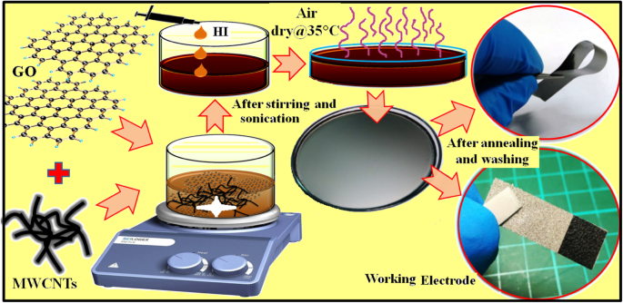
rGO/MWCNT 필름을 합성하기 위해 계산된 양의 GO 플레이크를 강력한 초음파 처리를 통해 탈이온수에 잘 분산시켜 8 mg/mL의 균질한 GO 분산액을 제조했습니다. 그 후, 0, 5, 10 및 15중량%의 MWCNT를 ~ 1 h의 강력한 초음파 처리를 통해 최적화된 양(20 mL)의 GO 분산액과 별도로 혼합했습니다. 상기 GO-MWCNT 혼합물에 환원제로서 최적량의 HI 용액을 한 방울씩 첨가하였다. 생성된 혼합물을 직경 ~ 9.5 cm의 페트리 접시에 붓고 기류에서 건조시켰다. 건조된 rGO/MWCNT 필름은 에탄올이 있는 경우 페트리 접시에서 쉽게 제거할 수 있습니다. 따라서, 얻어진 독립형 rGO/MWCNT 필름을 에탄올로 여러 번 세척하여 미반응/잔류 HI 용액을 제거하고 다시 35°C에서 12시간 동안 공기 중에서 건조시켰다. 마지막으로, 공기 건조된 프리스탠딩 필름은 환원 환경(3% H2 + 97% N2 ) 2 시간 동안. 전체 합성 공정의 개략도는 그림 1에 나와 있습니다. 다른 MWCNT 양(0, 5, 10 및 15wt%)으로 제작된 rGO/MWCNT 필름을 각각 GP, GP5C, GP10C 및 GP15C라고 합니다. <그림>
rGO, rGO/CNT 종이 및 전극 제조 공정의 합성 계획
rGO/MWCNT 전극 제작
전기화학적 시험을 위한 rGO/MWCNT 필름의 작동 전극은 조각(1 × 1cm
2
) 2 분 동안 균일한 ~ 10 mPa의 압력으로 Ni 발포체 위에 제작된 필름. ~ 0.1 μg의 정확도로 마이크로 저울(PRECISA XR125M-FR)로 측정한 Ni 발포체 기판에 로딩된 활성 물질의 중량은 ~ 1.1 mg였습니다. 합성 과정 및 전극 제조는 그림 1에 나와 있습니다.
GP10C 필름 기반 대칭 코인 셀 및 솔리드 스테이트 플렉서블 장치 제작
GP10C 전극 기반 대칭 슈퍼커패시터는 2 M KOH 전해질을 사용하는 2전극 코인 셀 구성으로 성공적으로 설계되었습니다. 간단히 말해서, 동일한 무게의 2개의 원형 GP10C 전극을 CR2032 코인 셀 어셈블리에 펀칭했습니다. 여기서 작업전극의 직접적인 접촉을 방지하기 위해 분리막(유리 극세사막, Whatman
TM
)가 그 사이에 끼어 있었다. 장치에서 활성 물질의 총 질량은 ~ 3.5 mg였습니다. 또한 유연한 장치에서 GP10C 전극 재료의 호환성을 확인하기 위해 PVA-KOH 겔 고분자 전해질을 사용하여 유연한 고체 상태 대칭 장치(FSSSD)를 설계했습니다. FSSSD의 제조를 위해 1 g PVA를 85°C에서 5 mL DI water에 녹이고 용액이 투명해질 때까지 1 시간 동안 교반한 후 1 g의 2 M KOH 용액을 상기 용액에 첨가하였다. 마지막으로, 혼합물을 3시간 동안 계속 교반하면서 방치하여 준고체 겔과 같은 형태를 얻었다[29]. 장치 조립용 2개(1 × 2cm
2
)의 동일한 무게의 GP10C 전극을 유연한 스테인리스 스틸 직물에 부착하여 전극이 기계적 충격을 받지 않도록 하고 외부 접촉을 지원합니다. 두 작업 전극 모두 겔 전해질과 같은 준고체로 균일하게 코팅되었습니다. 적절한 고체 젤과 같은 층을 얻기 위해 두 작업 전극을 흄 후드에서 공기 건조하여 물의 접근을 제거하고 서로 마주보고 끼우고 마지막으로 접착 테이프로 감쌌습니다.
물리-화학적 특성화 및 전기화학적 측정
준비된 rGO/MWCNT 필름은 CuKα 조사(λ =1.54184 Å, 10 mA 및 30 kV) 및 전계 방출 주사 전자 현미경(FE-SEM, Hitachi SU8010)은 각각 결정질 및 표면 형태 분석을 수행합니다. 샘플의 라만 스펙트럼 측정은 514.5 nm Ar 레이저, 40 mW(Horiba Jobin Yvon Labarm HR 800)를 사용하여 수행되었습니다. BET(Brunauer-Emmett-Teller) 표면적 분석기(BET, ASAP 2020)를 사용하여 비표면적을 식별했습니다. 열 중량 분석(TGA)은 3 °C min
−1
에서 30~900 °C에서 수행되었습니다. N2 미만의 램핑 속도 열중량 분석기(TGA, TA Instruments Q500)를 사용하는 환경. 합성된 필름의 옴 저항은 4점 프로브 방법(NAPSON RT-7)을 통해 측정되었으며 전기 전도도는 다음 식을 사용하여 계산됩니다.
$$ \sigma =\frac{l}{\mathrm{Rs}\times A} $$ (1)
여기서 σ, l, A, 및 Rs는 각각 4점 프로브 기기를 통해 측정한 합성 필름의 전기 전도도, 두께, 단면적 및 옴 저항을 나타냅니다. rGO/MWCNT 필름 전극의 전기화학적 특성은 실온에서 CHI 기기 616B 전기화학 분석기를 사용하여 순환 전압전류법(CV), 정전류 충전/방전(GCD) 및 전기화학 임피던스 분광법(EIS)에 의해 조사되었습니다. 포화 칼로멜 기준 전극(SCE), 상대 전극으로 백금 시트 및 작업 전극으로 rGO/MWCNT 필름을 포함하는 3전극 구성이 KOH, LiOH 및 NaOH의 전해질에서 이러한 측정에 사용되었습니다. GCD 곡선의 SC(Cs)는 다음 방정식을 사용하여 계산됩니다.
$$ C=\frac{I\ \Delta t}{m\ \Delta V} $$ (2)
나 방전 전류, ∆t 완전 방전을 위한 시간입니다. m 는 활성 전극 물질의 질량, 그리고 ∆V 대표 완전 방전을 위한 잠재적 창의 너비입니다.
전기화학적 임피던스 분광법(EIS) 결과는 0.1 Hz ~ 100 KHz의 주파수 범위에서 5 mV의 교류 진폭을 적용하고 결과 전류의 진폭과 위상 편이를 측정하여 얻었습니다. 바람직하게는, 슈퍼커패시터는 커패시터와 직렬로 연결된 저항을 갖는 간단한 회로로 상징화될 수 있다. 여기서 저항과 커패시터는 각각 소자의 등가직렬저항(ESR)과 커패시턴스를 나타낸다. 이 회로의 순 임피던스는 다음과 같이 표현할 수 있습니다.
$$ {Z}_{\mathrm{RC}}=R+1/ j\오메가 C $$ (3)
여기서, ω =2πf 그리고 f =주파수(Hz). 방정식 (3)은 더 높은 주파수 값에서 ESR 용어가 우세한 반면 더 낮은 주파수 값에서 용량성 용어가 더 효과적이 되고 시스템이 순수한 커패시터처럼 동작하기 시작한다는 것을 보여줍니다. 또한 EIS 데이터 분석은 아래와 같이 복소 전력 측면에서 슈퍼커패시터 전극 재료의 주파수 종속 특성을 제공합니다.
여기서 T 절대 온도, n 요금 이전 번호, R 기체 상수, C*를 나타냅니다. 는 전해질의 농도이며 A 작동 전극의 면적을 나타냅니다.
결과 및 토론
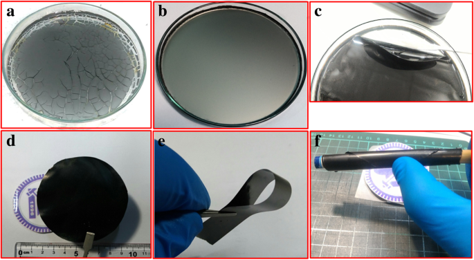
우리는 효율적인 1단계 화학 경로를 통해 rGO/MWCNT 기반 나노복합체 필름을 합성했습니다. 일반적으로 rGO 기반 나노복합체는 에너지 저장 물질로 잘 알려져 있다. 또한, 문헌에 보고된 바와 같이 MWCNT는 재료 내부에 전도성 채널을 설정하는 데 사용되었습니다[31]. 따라서 우리는 독립형 rGO 기반 필름의 전기 화학적 성능에 대한 MWCNT의 통합 효과를 연구합니다. 우리는 연속 전도성 독립 rGO/MWCNT 필름을 얻기 위해 HI(환원제)의 양이 중요하다는 것을 관찰했습니다. 최적 값보다 약간 더 많은 양은 과도한 양의 HI가 더 많은 I2를 유발하므로 필름에 균열이 남습니다. 해방하다 (HI + H2 O → H3 O
+
+ I
−
, 그리고 2I
−
=I2 + 2e
−
), 이는 그림 2와 같이 필름에 균열을 일으킬 수 있습니다.
<그림>
아 금이 간 rGO/MWCNT 필름, b 균일한 필름, c 페트리 접시에서 제거된 균일한 필름 및 d –f 세척 및 어닐링된 독립 필름
구조 및 형태적 특성
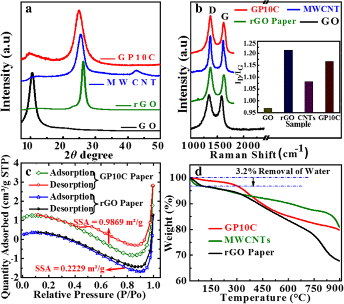
GO, rGO 필름, MWCNT 및 GP10C의 XRD 패턴은 그림 3a에 나와 있습니다. XRD의 포괄적인 특성은 준비된 필름의 탈산소화를 나타냅니다. GO 필름의 XRD 패턴은 2θ에서 날카로운 회절 피크를 나타냅니다. =10.4°, GO의 특성 (001) 회절에 해당합니다. 이것은 더 큰 층간 간격(d =0.8465 nm) GO 시트 표면에 부착된 산소 함유 작용기(예:에폭시 및 히드록실기)의 도입 및 단일 분자 두께의 존재로 인해 흑연(~ 0.34 nm)보다 GO 시트 사이에 삽입된 물 분자 층 [32,33,34]. rGO, MWCNT 및 GP10C 샘플의 경우 회절 피크가 2θ에서 나타납니다. =26.24°, 25.49° 및 25° 각각. 산화 그래핀의 성공적인 환원은 산소 함유 작용기의 파괴로 인한 rGO(~ 0.3475 nm) 및 GP10C(~ 0.36 nm)에서 층간 간격의 상당한 수축에 의해 분명합니다. rGO/MWCNT 필름의 라만 분석(그림 3b)은 각각 결함 및 무질서와 관련된 특성 G 및 D 밴드에 의해 GO, rGO, MWCNT 및 GP10C의 구조를 추가로 탐색하기 위해 실행됩니다. 그래핀 관련 물질에서 나타나는 결함을 관찰하기 위해 강도비(ID /나G ) D 밴드의 경우(1350 cm
−1
에서) ) 및 G 밴드(1590 cm
−1
에서 )가 일반적으로 사용된다[35]. 나D /IG 비율(삽입, 그림 3b)은 GO 필름의 경우 0.9685에서 rGO 종이, MWCNT 및 GP10C의 경우 각각 1.2123, 1.0807 및 1.1649로 증가하여 순수한 GO 필름보다 rGO, MWCNT 및 GP10C 필름에 더 많은 결함이 있음을 나타냅니다. 결함의 향상은 아마도 그래핀 시트가 더 작은 sp
2
로 분해되기 때문일 것입니다. 그래핀 도메인과 산소 함유 그룹의 분해로 인한 탄소 원자 손실 [36]. 나의 가치 D /나G GP10C 필름의 비율은 sp
2
증가에 기인할 수 있는 rGO 필름(1.2123)보다 작습니다(1.1649). 탄소나노튜브 도입으로 인한 도메인 [37]. N2 5분 동안 10.0 MPa의 균일한 압력을 가한 후의 rGO 및 GP10C 필름의 흡착-탈착 등온선은 그림 3c에 나와 있습니다. GP10C에 대해 계산된 BET 비표면적(0.9869 m
2
/g)는 rGO 필름(0.2229 m
2
)보다 4배 이상 높습니다. /G). 더 높은 비표면적은 전해질 이온과 전극 활물질 사이의 더 많은 계면 영역의 가용성을 예측하고 더 나은 전기화학적 성능을 제공할 수 있습니다[38]. 더 높은 비표면적은 외부 압력을 가할 때 rGO 시트가 다시 쌓이는 것을 방지하는 rGO 층 사이에 끼워진 MWCNT 때문일 수 있습니다. 열적 안정성을 조사하기 위해 합성된 필름의 TGA는 N2 3 °C min
−1
램핑 속도로 환경 30 ~ 900 °C(그림 3d). TGA 그래프에서 30~255°C에서 3.2% 중량 손실은 표면 흡수된 물의 증발 및 중간층 물 분자의 제거와 관련이 있습니다[39]. 302~810 °C 범위에서 약 18.6%의 중량 손실은 정제 및 합성 과정에서 rGO 및 MWCNT에 부착된 친수성 작용기의 분해 및 환원그래핀옥사이드 및 탄소의 열분해에 기인할 수 있습니다. 나노튜브[40]. 우리는 GP10C 필름의 열 안정성이 순수 rGO 필름의 열 안정성보다 우수함을 관찰했습니다. 이는 순수하게 독립형 GP10C에 MWCNT가 존재하기 때문일 수 있습니다.
<그림>
GO, rGO 종이, MWCNT 및 GP10C 필름의 XRD 패턴. 아 , b D 및 G 밴드의 라만 스펙트럼 진화, c rGO, rGO/CNT 필름 및 d의 BET 분석 rGO 필름, MWCNT 및 GP10C 필름의 TGA 곡선
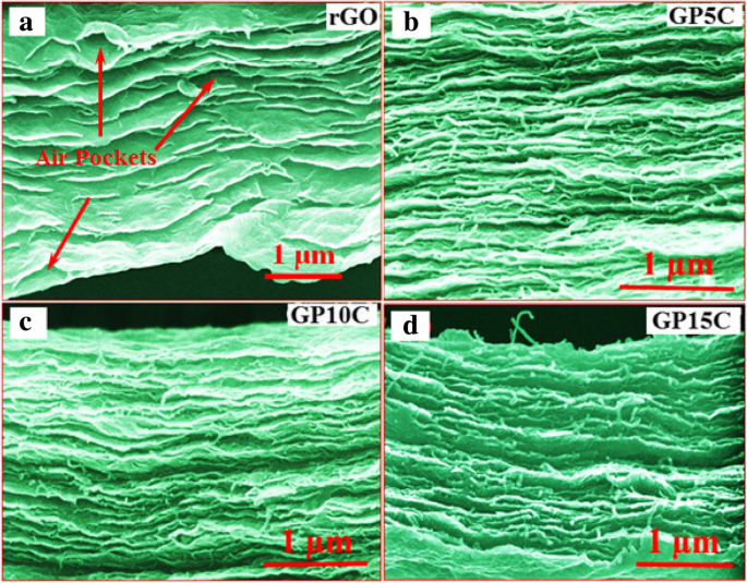
rGO 및 rGO/MWCNT 필름의 FESEM 현미경 사진은 그림 4에 나와 있습니다. 단면 검사(그림 4a)는 rGO 시트가 정렬되고 rGO 필름에서 다른 시트 위에 다시 쌓인다는 것을 보여줍니다. 환원 및 어닐링 과정에서 산소 및 기타 기체 종의 유리로 인해 발생하는 rGO 층 사이에 일부 에어 포켓의 존재를 관찰합니다. 이러한 공기 주머니는 전기 전도도를 감소시켜 독립 필름의 전기화학적 성능을 감소시킵니다[41]. 우리는 필름에 MWCNT를 추가하면(그림 4b-d), MWCNT가 필러로 작동하고 필름에서 나오는 가스 종에 대한 교대 경로를 제공함에 따라 rGO 층이 더 작은 에어 포켓과 정렬되는 것을 관찰합니다. <그림>
a의 단면 FE-SEM 이미지 다른 MWCNT가 로드되는 rGO 필름 b 5 wt.%, c 10 wt.% 및 d 15 중량%
전기 전도도 측정
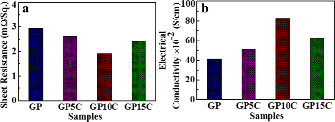
전기 전도도는 준비된 rGO 및 rGO/MWCNT 필름의 전기화학적 성능을 조사하는 데 매우 중요한 매개변수입니다. GP, GP5C, GP10C 및 GP15C의 두께가 각각 약 0.01, 0.015, 0.014 및 0.0165 mm인 전기 측정은 4점 프로브 장비를 통해 수행되었으며 측정된 GP, GP55C, GP10C 및 GP1의 오믹 저항은 다음과 같습니다. 각각 2.94, 2.71, 1.93 및 2.66 mΩ/sq.인 것으로 나타났습니다(그림 5a). 그림 5b는 Eq.에 의해 계산된 전기 전도도 값을 보여줍니다. (1) GP, GP5C, GP10C 및 GP15C의 경우 41.7 × 10
−2
, 51.4 × 10
−2
, 82.9 × 10
−2
및 62.9 × 10
−2
S cm
−1
, 각각. 필름의 전기 전도도는 MWCNT 비율이 0에서 10 wt.%로 증가함에 따라 증가합니다. 이것은 필름에서 MWCNT에 의해 형성된 전기 전도 네트워크의 존재에 기인할 수 있습니다. rGO 필름에 MWCNT를 추가하면 필름 내부의 전하 수송을 위한 전도 채널로 작동하는 3D 네트워크가 형성되어 전기 전도성이 향상됩니다. rGO에서 MWCNT의 로딩이 증가함에 따라 MWCNT의 정렬이 덜 뚜렷해집니다(그림 4b-d). 더 높은 MWCNT 농도(15 wt.%)에서, rGO 층 사이의 MWCNT의 응집 경향은 필름 전체에 걸쳐 MWCNT의 전도성 네트워크 형성을 감소시키는 효과가 있어 전기 전도도 값이 감소합니다[42]. 이는 기본적으로 접촉 저항 증가 효과에 기인한다[43, 44]. 다양한 합성 필름 중에서 GP10C는 82.9 × 10
−2
의 높은 전기 전도도와 함께 낮은 저항값(1.93 mΩ/sq.)을 나타냅니다. S cm
−1
. GP10C의 전기 전도성 향상은 강한 π의 결과입니다. -π 더 많은 모바일 충전 경력을 촉진하는 rGO와 MWCNT 간의 결합은 두 전자 밀도 사이의 비편재화를 촉진합니다[45].
<그림>
아 5, 10 및 15 wt.% MWCNT 함량 및 b를 포함하는 rGO 및 rGO/MWCNT 용지의 저항 동일한 전기 전도도
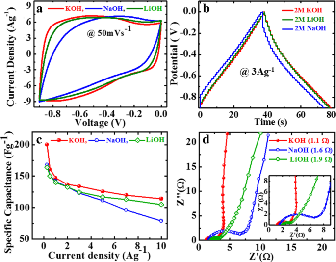
다양한 알칼리 전해질에서 GP10C 필름의 전기화학적 성능
GP10C 필름의 전기화학적 특성 측정은 실온에서 CV, GCD 및 EIS를 통해 수성 전해질에서 수행되었습니다. 전해질은 슈퍼커패시터의 전기화학적 특성에 큰 영향을 미치는 가장 중요한 요소 중 하나이다. 따라서 필름 전극에 가장 적합한 알칼리 전해질을 찾기 위해 가장 일반적으로 사용되는 세 가지 알칼리 전해질에서 GP10C 전극의 전기화학적 성능을 조사합니다. , 즉 KOH, NaOH 및 LiOH이며 결과는 그림 6에 나와 있습니다. 다른 전해질에 대해 CV 곡선은 다른 영역을 차지합니다(그림 6a). GP10C의 CV 곡선은 모양이 거의 직사각형이며 50 mVs
−1
의 스캔 속도에서 측정할 때 NaOH 및 LiOH보다 KOH에서 더 큰 영역을 차지합니다. . 도 6b에서, 3 Ag
-1
의 전류 밀도에서 GP10C의 GCD 곡선 NaOH 및 LiOH 전해질에 비해 KOH에서 더 긴 방전 시간을 보여줍니다. 식에서 분명합니다. (2) 방전 시간이 길어질수록(Δt ), SC가 높을 것입니다. 따라서 2 M LiOH 및 NaOH 전해질에 비해 2 M KOH에서 더 높은 SC를 얻습니다(그림 6c). GCD 곡선에서 관찰된 비대칭(그림 6b)은 복합 필름 표면에서 일부 패러딕 반응의 발생으로 인해 발생합니다. 이 현상은 rGO 시트 및 기능화된 MWCNT에 부착된 산소 함유 작용기에 기인할 수 있습니다. EIS는 기본적으로 이온 전달 및 전기 전도성 측면에서 필름의 전기화학적 성능을 실행하는 데 사용됩니다. 다른 전해질에서 GP10C의 Nyquist 플롯은 5 mV의 ac 진폭으로 0.1 Hz ~ 100 KHz의 주파수 범위에서 검사됩니다(그림 6d). GP10C의 Nyquist 플롯은 기본적으로 두 가지 주요 구성요소를 포함합니다(실수부 Z′ 및 허수부 Z″ ) Z'가 옴 거동을 나타내는 복잡한 평면을 나타냄; 한편, Z''는 필름 전극의 용량성 거동을 나타낸다. 이론적으로 고주파 영역(임피던스 아크), 저주파 영역 및 중간 주파수 영역(Warburg 임피던스)의 세 가지 주파수 종속 영역을 통해 이론적으로 설명할 수 있습니다.
<그림>
2 M 전해질의 다양한 수성 KOH, LiOH 및 NaOH에서 GP10C 필름의 전기화학적 성능, a 50 mVs
−1
에서의 CV 곡선 , b 3 Ag
−1
에서의 GCD 곡선 , ㄷ GCD 곡선에서 계산된 SC 및 d 확대된 영역을 보여주는 삽입이 있는 다양한 전해질의 Nyquist 플롯
슈퍼커패시터는 고주파수 범위에서 순수 저항과 유사하게 작동하는 반면, 저주파에서는 허수부의 급격한 증가와 거의 수직선이 관찰되어 순수한 정전용량 동작을 나타냅니다. 중간 주파수 영역은 전해질 이온과 필름 전극의 다공성 활성 부위 사이의 상호 작용을 나타냅니다. 또한 EIS에서는 전해질의 이온 저항, 집전체와 활물질의 내부 저항, 전극-집전체 계면 접촉 저항이 유효 직렬 저항(ESR) 또는 용액 저항(Rs)을 찾는 데 중요한 역할을 합니다. Nyquist 곡선의 고주파수 영역에서 곡선이 실제 축과 교차하는 점 값으로 ESR을 관찰할 수 있습니다. Rs 값은 NaOH(~ 1.6 Ω) 및 LiOH(~ 1.9 Ω)에 대해 측정된 값보다 KOH에 대해 더 작은(~ 1.1 Ω) 것으로 밝혀졌습니다. 또한 고주파 영역에서 반원호의 지름과 중간 주파수 영역에서 45° 각도의 경사선 길이가 각각 확산 저항과 바르부르크 저항을 대표한다는 점에 주목해야 합니다. 이와 관련하여 GP10C는 LiOH 및 NaOH에 비해 KOH에서 더 작은 확산 저항과 Warburg 저항을 나타냅니다[46, 47]. KOH에서 GP10C 전극의 우수한 성능은 K
+
의 더 작은 수화된 이온 반경 및 더 높은 이온 전도도와 관련될 수 있습니다. 이온(64.3옴
−1
cm
2
몰
−1
) Na
+
에 비해 (43.5옴
−1
cm
2
몰
−1
) 및 Li
+
(33.5옴
−1
cm
2
몰
−1
) 이온. 반면에, K
+
의 낮은 수화된 이온 반경에 의해 강화된 이온 이동도 이온은 전극 표면에 접근하여 GP10C 전극의 전기화학적 성능을 향상시킵니다[48, 49]. K
+
에 대한 간단한 설명 , 나
+
및 Li
+
수화된 이온 반경이 각각 232, 276 및 340 pm인 이온은 그림 7에 나와 있습니다. 외부 요인보다 실제 이온 반경은 공식 F =KQ1질문2 /r
2
, 여기서 F 는 쿨롱 힘, r 두 전하 사이의 거리입니다(Q1 및 Q2 ) 및 K 는 쿨롱 상수입니다. 이온 반경은 rK+ (=138 pm)> rNa
+
의 순서를 따릅니다. (=102 pm)> r Li
+
(=76 pm)이므로 쿨롱 힘은 K
+
차수를 따릅니다. <나
+
<리
+
. 더 큰 쿨롱 힘은 더 많은 수의 물 분자와 결합하여 수화된 이온 반경을 더 크게 만듭니다[50, 51], 따라서 K
+
이온은 더 낮은 수화된 이온 반경을 갖는다. On the basis of the above results and discussion, KOH aqueous electrolyte is found as a mostly suitable electrolyte among the three studied electrolytes for the rGO/MWCNT film electrode.
Schematic diagram of hydrated ionic radii of the ions associated with different electrolytes used for GP10C electrode measurement
Electrochemical Performance of rGO/MWCNT Films
We also investigated the effect of MWCNT addition on the electrochemical performance of rGO/MWCNT films in a three-electrode setup with 2 M KOH electrolyte. Figure 8a depicts the CV curves of as-synthesized rGO, GP5C, GP10C, and GP15C film electrodes recorded at a scan rate of 50 mVs
−1
in the potential range − 0.9 to 0.0 V. Evidentially, in comparison to GP, GP5C, and GP15C, the CV curve of GP10C occupies the larger area, and it belongs to nearly rectangular shape, implying the electrical double-layer (EDL) capacitive behavior of this electrode with higher SC value [52]. Figure 8b represents the GCD curves of all the films recorded at 1 Ag
−1
in the potential range − 0.9 to 0.0 V. Furthermore, similar to CV results, the charge/discharge curves being nearly triangular in shape also verify the electrical double-layer capacitor (EDLC) behavior of the film electrodes. Here, it is clear that the GP10C has significantly longer discharge time (∆t ), and hence higher SC among the synthesized films. The values of CVs calculated from the GCD curves using Eq. (2) as function of discharge current densities are shown in Fig. 8c. The GP10C exhibits specific capacitances of 200, 161, 147, 137, 134, 123, 120, and 114 Fg
−1
at 0.25, 0.5, 1, 2, 3, 5, 7, and 10 Ag
−1
, respectively, and it is able to maintain ~ 57% of its initial capacitance value (200 Fg
−1
) from 0.25 to 10 Ag
−1
. The specific capacitance of rGO increases significantly after the addition of MWCNTs, which is obvious from the electrochemical performances of GP5C and GP10C samples. The improved electrochemical performances of the composite can be ascribed to the fact that CNTs prevent the restacking of rGO sheets and hence facilitate the electrolytic ions to move deeper into the film samples. As the amount of CNTs is increased beyond the optimum value, specific capacitance decreases, which can be ascribed to the limited dispersibility and poor specific capacitance (~ 20 F/g) of MWCNTs [53, 54].
Electrochemical performance of rGO, GP5C, GP10C, and GP15C electrodes in 2 M KOH electrolyte, a CV curves at the scan rate of 50 mVs
−1
, b GCD curves at the current density 1 Ag
−1
, ㄷ CV as determined from GCD curves, and d Nyquist plots comparison of all the papers
Moreover, the specific capacitance of all the synthesized films decreases with an increase in the current density because the diffusion of electrolytic ions into the film electrodes becomes slower at higher current density values. Figure 8d shows the Nyquist plots of all the electrodes, indicating that with an increase of MWCNT content, internal resistance starts to decrease. The internal resistance is the Ohmic resistance, which consists of ionic resistance of electrolyte, inherent resistance of substrate and active electrode material, and contact resistance at the active electrode material and substrate interface. GP10C film electrode demonstrates the smallest internal resistance (1.14 Ω), while the internal resistances for rGO, GP5C, and GP15C are found to be about 2.2, 1.41, and 1.19 Ω, respectively. The smaller value of internal resistance for GP10C film can be ascribed to the better contact and its higher electrical conductivity. The “knee” frequency is defined as the highest frequency value at which impedance of the system is dominated by the capacitive nature [55]. It is related to the diffusion coefficient and effective diffusion length of the active electrode material. Further, at the frequencies higher than knee frequency, the electrolytic ions come across semi-infinite diffusion and finite diffusion at the frequencies lower than this [56, 57]. The knee frequency values for GP5C, GP10C, and GP15C are 1.37, 1.49, and 1.10 Hz, respectively. The higher knee frequency value for GP10C implies that lesser time is required by the charge species to accumulation at the interface for this sample. Further, it is well documented that larger semicircle at higher-to-medium frequency region corresponds to the larger charge-transfer resistance (Rct) [31, 58]. The Rct for GP15C film seems to be quite higher than that of GP10C, that may be due to its lower electrical conductivity and higher contact resistance with aqueous electrolyte [59].
Further, EIS data can be used to find out the relaxation time constant (τ0 ) of the devices like supercapacitors in terms of complex power with the help of Eqs. (8) and (9). Relaxation time constant (τ0 ) is an important parameter and considered as a factor of merit for a supercapacitor. To determine the relaxation time constant, normalized imaginary factor (|Q |/|S |) and real factor (|P |/|S |) of power are plotted vs. frequency (in logarithmic scale) (Fig. 9). Both these two curves cross each other at a point called resonance frequency (f° ), which is utilized to calculate the relaxation time of a supercapacitor using the following formula:τ0 = 1/2πf0 [49]. From the graphs, we observe that at a higher frequency, |P |/|S | attains maximum value, which implies maximum power dissipates in the system, i.e., supercapacitor behaves similar to pure resistor. As the frequency decreases, |P |/|S | decreases up to a point at which |Q |/|S | attains the highest value. At this point, supercapacitor works similar to a pure capacitor. Evidently, for all the tested films GP(rGO), GP5C, GP10C, and GP15C, both the |P|/|S| and |Q|/|S| curves act contrarily with frequency variation and cross each other at resonance frequency (f° ). The relaxation time constant values for GP, GP5C, GP10C, and GP15C as calculated using resonance frequencies are 1.3 s, 196 ms, 194 ms, and 378 ms, respectively. After adding MWCNTs in the rGO film, relaxation time decreases remarkably. This may be due to the fact that CNTs prevent the restacking of rGO sheets and hence allow the electrolytic ions to move faster into the film. As the amount of MWCNTs increases further (15 wt%) in the rGO film, increment in the relaxation time constant is observed. This can be ascribed to the smaller diameter of MWCNTs (10–20 nm) that offers higher ionic diffusion resistance, which become significant as the amount of MWCNTs is increased beyond optimum value [60, 61]. EIS results can also be used to determine the diffusion coefficients of the synthesized films for electrolytic ions (Fig. 9d). The calculated diffusion coefficients (D아 ) of electrolytic ions at the interfacial region using Eq. (7) come out to be 1.0112 × 10
−13
, 8.0286 × 10
−9
, 7.8457 × 10
−9
, and 2.1919 × 10
−9
for GP, GP5C, GP10C, and GP15C, respectively, in 2 M KOH. It can be seen that the relaxation time constant and diffusion coefficient of GP5C and GP10C are almost the same, but the Cs and rate capability of GP10C is much better than those of GP5C. The small relaxation time constant and high diffusion coefficient of GP10C film electrode, allow it to deliver stored energy quickly, and high specific capacitance make it desirable for engineering high-power capacitors.
아 –ㄷ are the normalized real part |P|/|S| and imaginary part |Q|/|S| of the complex power as a function of frequency for GP, GP5C, and GP10C, respectively, and d Randles plots of all the synthesized electrodes
From the above results, GP10C film-based supercapacitor electrode exhibits the best electrochemical properties among the synthesized films. Therefore, we investigate its electrochemical performance in detail. Figure 10a indicates the CV curves of GP10C at 5, 10, 25, 50, and 100 mVs
−1
in the potential range − 0.9 V to 0.0 V vs Ag/AgCl reference electrode. It is shown that all the CV curves possess almost rectangular and symmetric shape, indicating the perfect EDL capacitive behavior and fast charging/discharging characteristics. The inset in Fig. 10a shows nearly a linear relationship between average peak current and the square root of the scanning rate with correlation coefficient R
2
= 0.98878. This phenomenon indicates that the electrochemical process in the film is a diffusion-controlled process [62]. Figure 10b represents the GCD curves of GP10C evaluated at 0.25 to 10 Ag
−1
in − 0.9 to 0.0 V. During the charge/discharge process, the corresponding curves also verify that the charging curve of GP10C is almost symmetric to its corresponding discharging curve. To evaluate the durability of the GP10C, the long cycle test was carried out in 2 M KOH electrolyte at 2 Ag
−1
. Figure 10c depicts the long cycle stability, which is another important parameter to examine the electrochemical performance of an electrode material. After 15,000 cycles, GP10C electrode exhibits excellent retention of 92.5%. The inset in Fig. 10c shows first and last 5 successive cycles. It demonstrates that even after 15,000 cycles, the electrode maintains good symmetric charge/discharge characteristic features, which verify its excellent electrochemical durability. Figure 10d represents the Nyquist plots of the GP10C electrode recorded during long cycle test. It can be observed that the value of internal resistance goes higher during cycling process from the first cycle to 15,000 cycles. GP10C electrode shows lowest internal resistance (1.12 Ω) during the first cycle and after 10,000 and 15,000 cycles, as the electrochemical active sites in the electrode are slowly consumed, the values of internal resistance increases from 2.64 to 3.04 Ω, respectively. As a consequence of it, CV value decreases slowly and repeatedly during electrochemical cycling (Fig. 10c). Furthermore, to find out any morphological changes in the GP10C film electrode after long cycle test, we performed ex situ studies (FESEM and TEM), and the results are shown in Fig. 11. Figure 11a shows the TEM images of GP10C electrode before the long cycle test, while Figs. 11b and c represent the FESEM and TEM images of the GP10C after 15,000 cycles. We can see that the morphology of the GP10C electrode does not change even after 15,000 cycles, which reveals the sustained chemical stability of the film. The observed capacitance of GP10C film electrode is higher than those of several recently reported free-standing graphene-based supercapacitor electrodes as shown in Table 1.
Electrochemical performance of GP10C in 2 M KOH electrolyte a CV curves at the scan rate of 5, 10, 25, 50, and 100 mVs
−1
; ㄴ GCD curves at the current densities of 0.25, 0.5, 1.0, 2.0, 3.0, 5.0, 7.0, and 10 Ag
−1
; ㄷ cyclic stability performance for GP10C electrode at 2 Ag
−1
and inset shows the GCD curves of first and last 5 cycles; 그리고 d Nyquist plot for the GP10C and inset shows the EIS performance during 1st, 10,000 and 15,000 cycles
아 TEM images of the CP10C electrode before long cycle test and b FESEM and c TEM images of the CP10C after 15,000 cycles
Electrochemical Performance of Symmetrical Supercapacitor
Further, to investigate the practical application of the GP10C film, we made a symmetric coin cell supercapacitor using two GP10C electrodes of identical weight separated by a separator in 2 M KOH aqueous electrolyte. Figures 12a and b show the CV profiles of the device at the scan rates of 2, 5, 10, 15, 25, 50, 75, and 100 mVs
−1
. We can observe nearly identical rectangular shape, which implies the perfect EDLC behavior of the supercapacitor. Figure 12c represents the linear GCD curves at all current densities demonstrating the high rate response of the device. Moreover, the smaller internal resistance (0.4 Ω) of the coin cell indicates better charge transportation in the supercapacitor (Fig. 12d). The calculated specific capacitances from CVs of the device (Fig. 12e) are 53, 51, 49.8, 48, 46.7, and 45 Fg
−1
at 0.1, 0.2, 0.3, 0.5, 0.7, and 1.0 Ag
−1
, 각각. From the capacitance profile (Fig. 12e), it is clearly shown that the device retains 85% of its initial capacitance value at current density 0.1 Ag
−1
up to 1 Ag
−1
, i.e., good rate capability. Additionally, we calculate the energy density (Whkg
−1
) and power density (Wkg
−1
) of the device using equations given below [8, 9]:
Electrochemical performance of GP10C/KOH/GP10C symmetrical coin supercapacitor cell a , b CV curves of GP10C/KOH/GP10C coin cell at 2, 5, 10, 15, 25, 50, 75, and 100 mVs
−1
, ㄷ Nyquist plot, d GCD curves of the device at different current densities, e SC at different current densities, f Ragone plot
where Cs is the SC calculated from the GDC curves, ∆V is the potential window, t is the discharge time (s).
The device exhibits maximum and minimum energy densities of 29.4 and 25.0 Whkg
−1
at power densities of 439 and 4500 Wkg
−1
, respectively (Fig. 12f).
This symmetric device shows excellent retention of ~ 85% and columbic efficiency of 92% after 10,000 successive cycles at 0.3 Ag
−1
(Fig. 13a). The excellent cyclability of the device can be ascribed to the electrochemical stability of the active electrode material. In the GP10C nanocomposite film, the optimum amount of MWCNTs mainly prevents the restacking of rGO sheets and thus offers a more exposed area to the electrolytic ions for surface adsorption. This also strengthens the material structure to resist the structural deformation upon cycling. The ex situ TEM and FESEM micrographs of the tested electrode after 15,000 cycles (Fig. 11a–c) verify the behavior that the morphology of GP10C electrode remains the same even after 15,000 cycles, which reveals the sustained chemical stability of the synthesized composite film. The inset in Fig. 13a shows the GCD profiles of 1st, 5000th, and 10,000th charge-discharge cycles, indicating the symmetric charge/discharge characteristic features of the device. The high retention at even after 10,000 continuous long cycles verifies its outstanding electrochemical durability. Figure 13b depicts the Nyquist plots of the device during long cycle test, implies that with repeated cycles, the Warburg region in the middle frequency region is increasing. It can be attributed to the consumption of active sites presented in the active material of the supercapacitor electrodes during a long cyclic test, which results in an increase of the internal resistance of the device. The inset (Fig. 13b) shows that our symmetric coin cell can light up a red LED. Further, our designed FSSSD using GP10C flexible film electrodes and gel electrolyte depicts no significant changes in the shape of CV curves when bending the device at angles from 0 to 180° at a scan rate of 20 mVs
−1
(Fig. 13c). Digital photographs of the device under the bending angles 0°, 60°, 90°, and 180° are shown in Fig. 13d–g, respectively.
The long cycle performance of GP10C/KOH/GP10C symmetrical coin cell. 아 Cyclic stability and columbic efficiency recorded at 0.3 Ag
−1
for 10,000 successive cycles, and inset shows the GCD profiles of 1st, 5000th and 10,000th GCD cycles. ㄴ Nyquist plots recorded just after 1st, 5000th and 10,000th cycles, and inset shows a red LED light up by single coin cell. ㄷ The CV curves at a scan rate of 20 mVs
−1
of symmetrical solid state flexible device using gel polymer electrolyte under different bending angles. Digital photographs of the device under different bending angles, d 0°, e 60°, f 90°,and g 180°, respectively
The above results prove the potential applications of our synthesized GP10C film for the supercapacitors. Moreover, this facile approach may open future prospects for energy storage devices application.
결론
In summary, simple and cost-effective rGO/MWCNT flexible film electrodes were synthesized via simplest chemical route. The effects of MWCNT addition on the electrochemical performance of rGO/MWCNT nanocomposite films were investigated in different alkaline electrolytes, KOH, LiOH, and NaOH. Based on experimental findings, GP10C exhibits the best electrochemical performance in 2 M KOH with SC of 200 Fg
−1
. This synthesized film electrode demonstrates excellent durability with 92% retention after 15,000 long cycle test, small relaxation time constant (~ 194 ms), and high diffusion coefficient (7.8457 × 10
−9
cm
2
s
−1
) in 2 M KOH aqueous electrolyte. The superior electrochemical performance of GP10C can be attributed to the smaller hydration sphere radius and higher ionic conductivity of K
+
양이온. The symmetric coin supercapacitor cell using GP10C as both anode and cathode and 2 M KOH as electrolyte exhibits perfect EDLC behavior with maximum energy and power densities of 29.4 Whkg
−1
and 4500 Wkg
−1
, 각각. Our symmetric cell demonstrates excellent retention of 85.3%, and columbic efficiency of 92% after 10,000 successive cycles at 0.3 Ag
−1
. Further, the designed FSSSD using GP10C flexible film electrodes and gel electrolyte depicts no significant changes in the shape of CV curves when bending the device at angles from 0 to 180° at 20 mVs
−1
. We believe that our rGO/MWCNT nanocomposite film is suitable for practical applications and appropriate for designing high capacitive energy storage (supercapacitors or Li-batteries), conversion, and wearable devices.
데이터 및 자료의 가용성
All data and materials are fully available without resection.